All Fets look a lot like Triodes at low Vds values, and cascoding is one way of
putting that to work, as the Vds can be set fairly arbitrarily.
The F3 did that by cascoding the LU1014 and setting the DC and AC Vds values
seen by the part. I recall that I was able to get some nice .00X% numbers that
way.

The F3 was the only circuit that gave the LU1014 an opportunity to be a nice
amplifier. I couldn't get any kind of performance with the other topologies.
I am thinking of using your F3 topology for an ESL headphone direct drive amp but at hundreds of volts rail supply and between 10V and 15V across the LU1014D. The idea would be to get as close as possible to a single ended triode sound using semiconductors. The performance may not be super low distortion, but you can probably say the same of a single ended triode.
There some nice SiC FETs in production that can withstand 650V to 1200V that would be the cascode devices.
From my cursory investigation, bias setting is 10mA-ish for such a beast.
I’ve been looking into cascoding mosfet.
The input capacitance goes through the roof at low Vds.
How do u deal with it?
The input capacitance goes through the roof at low Vds.
How do u deal with it?
> The F3 was the only circuit that gave the LU1014 an opportunity to be a nice amplifier.
> I couldn't get any kind of performance with the other topologies.
Maybe not for power amps. But it makes a really wonderful follower for headphones. 🙂
DAO - Original-Ton
The DAO SE all-FET Class-A ZGF Headphone Amplifier
Patrick
> I couldn't get any kind of performance with the other topologies.
Maybe not for power amps. But it makes a really wonderful follower for headphones. 🙂
DAO - Original-Ton
The DAO SE all-FET Class-A ZGF Headphone Amplifier
Patrick
Hey guys,
Found this one from Toshiba. Curves look ok for an audio implementation?:
https://www.mouser.ch/pdfDocs/TW070J120B_datasheet_en_20200805.pdf
Datasheet was released in August 2020
Found this one from Toshiba. Curves look ok for an audio implementation?:
https://www.mouser.ch/pdfDocs/TW070J120B_datasheet_en_20200805.pdf
Datasheet was released in August 2020
it seems interesting,but from graphs only, we can expect at least 8V of Ugs for, say, 2A@20V
no bueno
no bueno
I’ve been looking into cascoding mosfet.
The input capacitance goes through the roof at low Vds.
How do u deal with it?
Capacitance is a mostly a problem when you have to charge it with the
audio signal, and cascode holds the voltage relatively constant, so more
bandwidth and better capacitive linearity. You can also improve that by
having a higher Vds in your cascode.
Most of the time it is that changing value of the capacitance vs voltage
and current that generates distortion. Usually bandwidth per se is not
the issue.
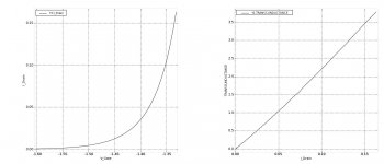
Woofertester, did you measure the Rd and Mu of that Ld1014d ?
I did not. Just did family of curves to verify that they are the genuine article.
At what voltage and current do you want Rd and Mu?
I was mainly concerned with about 12v and between 50 and 100 ma.
At 12V Vds, the device behaves erratically. I am guessing I need a chunk of metal attached.
At 7V, I can get good curve traces.
At 7v and 51mA, gm = 0.95, Rd (V / I) is 138 ohms and Mu is 130
This is just the first pass at dialing in these measurements. Feel free to critique.
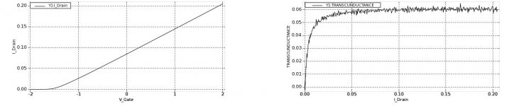
Next step. Choose bias conditions of Vds=7V, bias current ~100mA. The self bias resistor will be ~13 ohms. I have some 15 ohm resistors in my stash. I placed a 15 ohm resistor from SOURCE to ground and ran the Vgs-Id plot and transconductance plot. They are attached.
The self bias point appears to be ~ 80 mA and the transconductance plot looks very linear with enough gain to almost fully drive rail-to-rail operation with 2v p-p input.
So, for a simple class-A headphone amp:
Voltage rail 14V
bias current 100mA
Source resistor ~ 13 ohms (0.13w power dissipation)
Drain resistor ~ 70 ohms (0.7w power dissipation)
gain > 60mA/V
This would be a starting point with adjustments to be made to achieve symmetric clipping if possible and adjustments for distortion character desired.
Attachments
So your "Vgs" includes voltage drop across the 15R resistor ?
Patrick
Yes. V_Gate is the voltage from gate to common LO. In post #34, there is a 15 ohm resistor from source to common LO. In post #33, there is no source resistor.
The linearity comes from the resistor, not the LU1014 itself.
To make use of the triode characteristics of the LU1014, see Nelson's Zen Version 9 article.
Patrick
To make use of the triode characteristics of the LU1014, see Nelson's Zen Version 9 article.
Patrick
Hello Patrick. Thank you for the nudge and the advice.
I did what you suggested and re-read Zen V9 as well as Zen V8.
I went back to the curve tracer and did some plotting and experimenting with different parts of the possible V-I space.
For a headphone amp with a bias in the 50mA to 100mA range, the attached plot looks to be the most "triodey" part of the possible V-I space. A good space looks to be Vds =6V and Id = 100mA. In the attached plot, from left to right, Vgs = -1.28v to -1.45v. For the operating point of Vds = 6V, Vgs ~ -1.32v
Attachments
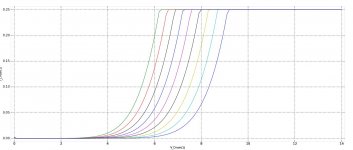
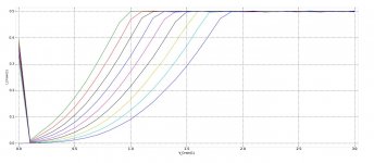
I am changing my mind. Looks just as triodey but lower gain.
I will say that the device looks triodey almost everywhere you would use it in an audio application. It is pentode looking where the device is fully on for a switching power supply.
I will say that the device looks triodey almost everywhere you would use it in an audio application. It is pentode looking where the device is fully on for a switching power supply.
Attachments
- Home
- Amplifiers
- Pass Labs
- United SiC UJ3N065080K3S, Is there any triode behavior?