Constant = Directivity index does not change through spectrum.
Uniform = Directivity index is smooth, but can increase through spectrum.
Uniform = Directivity index is smooth, but can increase through spectrum.
Call me stupid but I don't understand the difference either 😕 😱
Can anyone please define "uniform" vs "constant"?
If there's any confusion about this still, I think it's fairly simple unless I'm mistaken.
Constant means completely flat both on and off axis. You don't see this much.
Uniform means flat response on axis but with a downward slope as frequency increases off axis. I prefer to call this controlled directivity.
Both of these terms are compared and contrasted to uncontrolled directivity, in which no attempt at all is made to control "tweeter bloom" and other effects that cause dramatic and very abrupt changes in off axis response.
EDIT - I guess some other people posted as I was typing.
I assumed that Wayne meant uniform power response in regards to directivity....at least that's how I read it.
If he wants to discuss directivity he has to be exact in his wording. That's exactly the point of my graph which really doesn't show anything meaningful about directivity, let alone if it's contant or uniform. It shows a radiation pattern but at what frequency? Without additional information the graph is meaningless.
Hello Wayne
Looking at the measurements are those on axis with no crossover?? Just raw CD and Horn/Waveguide measurements??
I think uniform directivity is important as well. If you look at the first JBL Biradials they were all optimized for pattern control. If you look at the 4430 measurements you can see the peaks in the horns range.
http://www.lansingheritage.org/images/jbl/specs/pro-speakers/1984-4430-35/page05.jpg
Rob🙂
To get straight to the heart of the matter, as I mentioned, IMO a waveguide is only one part in a system composed of many different parts. IMO, looking at the response of this one part doesn't show the whole picture. It's useful to sort out obviously flawed waveguides but it's only a small part of a big picture.
Ideally each one of us would make a determination based on technical information and listening to each speaker in a variety of different environments. Since the latter isn't feasible in most cases all we can do is peruse the available technical data.
Ideally we would look at the parameters in question (distortion and frequency response on and off axis) of competently designed full systems. I'm not going to spend all day looking for examples of these measurements so I'll just point to some info that I could locate very easily and invite advocates of both sides to provide more data and critique the data objectively.
Starting here:
So who's going to build Jeff Bagby's Definimax-12/SEOS Econowave? - Page 2
and all the way to post 52 there's a bunch of on axis measurements of the SEOS, both alone and as part of a system. Post 27 and 52 have distortion information, waveguide alone and as part of a system.
Unfortunately there's no off axis info presented here but the designer states that there's not much need since the off axis behavior is well documented and his will look a lot like info presented elsewhere.
This is a respected source that knows how to measure and design and he's got nothing to gain by presenting the info, so his contributions should be valid and unbiased. This info can be directly compared and contrasted to other products.
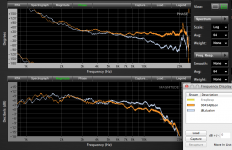
Here's an example that I posted previously, the Fusion 15 on and off axis response:

I'd rather post info of the 12 inch waveguide but I'm not going to spend all day looking for it. As part of a system, the response both on and off axis looks reasonably flat. Not perfect (there's a bit of bunching in some areas) but really not bad, especially for a $400 kit including all parts including crossover parts and cnc baffle. I don't see any large frequency response anomalies on or off axis, and I'm paying special attention to the 1 - 4 khz area since it's so important.
I don't know where the Pi info is (I assume it's all in the link Wayne posted earlier but I'm not going to go through dozens of links to find it - and I'm not familiar with any of the Pi products).
This is system data. IMO it's more important than raw data of individual parts. I invite more people to post more system data and critique it. I don't think anyone can argue that the SEOS response is a bit of a roller coaster ride with 5 db variation from the lowest point in the valleys to the highest spot in the peaks IN THE RAW RESPONSE but that doesn't seem to matter much in a complete system designed by a competent designer. If I'm missing anything please educate me.
Ideally each one of us would make a determination based on technical information and listening to each speaker in a variety of different environments. Since the latter isn't feasible in most cases all we can do is peruse the available technical data.
Ideally we would look at the parameters in question (distortion and frequency response on and off axis) of competently designed full systems. I'm not going to spend all day looking for examples of these measurements so I'll just point to some info that I could locate very easily and invite advocates of both sides to provide more data and critique the data objectively.
Starting here:
So who's going to build Jeff Bagby's Definimax-12/SEOS Econowave? - Page 2
and all the way to post 52 there's a bunch of on axis measurements of the SEOS, both alone and as part of a system. Post 27 and 52 have distortion information, waveguide alone and as part of a system.
Unfortunately there's no off axis info presented here but the designer states that there's not much need since the off axis behavior is well documented and his will look a lot like info presented elsewhere.
This is a respected source that knows how to measure and design and he's got nothing to gain by presenting the info, so his contributions should be valid and unbiased. This info can be directly compared and contrasted to other products.
Here's an example that I posted previously, the Fusion 15 on and off axis response:
I'd rather post info of the 12 inch waveguide but I'm not going to spend all day looking for it. As part of a system, the response both on and off axis looks reasonably flat. Not perfect (there's a bit of bunching in some areas) but really not bad, especially for a $400 kit including all parts including crossover parts and cnc baffle. I don't see any large frequency response anomalies on or off axis, and I'm paying special attention to the 1 - 4 khz area since it's so important.
I don't know where the Pi info is (I assume it's all in the link Wayne posted earlier but I'm not going to go through dozens of links to find it - and I'm not familiar with any of the Pi products).
This is system data. IMO it's more important than raw data of individual parts. I invite more people to post more system data and critique it. I don't think anyone can argue that the SEOS response is a bit of a roller coaster ride with 5 db variation from the lowest point in the valleys to the highest spot in the peaks IN THE RAW RESPONSE but that doesn't seem to matter much in a complete system designed by a competent designer. If I'm missing anything please educate me.
Last edited:
To get straight to the heart of the matter, as I mentioned, IMO a waveguide is only one part in a system composed of many different parts. IMO, looking at the response of this one part doesn't show the whole picture. It's useful to sort out obviously flawed waveguides but it's only a small part of a big picture.
I agree generally, but I also would suggest that the system is only as good as its weakest link. Some things you can fix in the implementation, some things you can't.
Ideally each one of us would make a determination based on technical information and listening to each speaker in a variety of different environments. Since the latter isn't feasible in most cases all we can do is peruse the available technical data.
Ideally we would look at the parameters in question (distortion and frequency response on and off axis) of competently designed full systems.
I agree with that also, but to compare honestly, you'll need to measure two systems in the same environment on the same measurement system, using the same types of tests and then present the data in a consistent manner. Otherwise, the presentation may be misleading. Not necessarily intentionally misleading, but still.
I've seen people look at charts that were just scaled differently and get a different impression from two presentations of the same data. It's compounded further when you have different measurement systems with different resolutions measured in different environments with different excitation signals.
I think it's telling when several measurements in a variety of conditions show a similar trend though. When I see that, I have high confidence in the validity of the data. Of course, when data is rendered in a low enough scale and/or resolution, it all tends to look like a straight line. So that doesn't sway me. On the other hand, when I see a signature in the detail of multiple charts, then I start to feel very confident that what I am seeing is reproducible and consistent.
Looking at the measurements are those on axis with no crossover?? Just raw CD and Horn/Waveguide measurements??
Yes, those charts are driver on waveguide, without crossover. Just LMS -> amp -> driver. Didn't even use a protection cap.
And I agree with you that uniform directivity is very important. Kinda been the main thing to me for years, as you know. But I do think it is really important that the horn not introduce excessive anomalies too.
I think constant directivity horns often trade some response ripple for pattern control, and I think some go a bit too far.
If you look at the 4430 measurements you can see the peaks in the horns range.
Yes, and that's my point. My goal is to take that design approach and improve upon it.
That's really what the whole "waveguide" movement is all about, in my opinion. The approach is to remove the diffraction slot from the throat, and in some cases, another diffraction edge nearer the mouth. Replace those with gentle curves. This still offers constant directivity - at least up to about 13kHz - but doesn't fracture the wavefront progression with an abrupt discontinuity.
Above 13kHz, the diffraction slot can still curve the wavefront, so I suppose it is the winner where pattern control is the main thing. But those early constant directivity horns had sharp discontinuities that caused internal reflections and ripples in response. They sound spitty to me. Some horns also have that horn honk thing from standing waves, and that sounds ugly to me too.
I know you're up on all this, you've been around forever. Just putting it on page for those that might not know the difference.
Last edited:
I agree generally, but I also would suggest that the system is only as good as its weakest link. Some things you can fix in the implementation, some things you can't.
Ok, but if the weakest link is stronger than it needs to be there isn't a problem. I've posted a few pics and links of implementation and I don't see a problem with them. But no one is commenting on the system graphs so...
I agree with that also, but to compare honestly, you'll need to measure two systems in the same environment on the same measurement system, using the same types of tests and then present the data in a consistent manner. Otherwise, the presentation may be misleading. Not necessarily intentionally misleading, but still.
I've seen people look at charts that were just scaled differently and get a different impression from two presentations of the same data. It's compounded further when you have different measurement systems with different resolutions measured in different environments with different excitation signals.
I think it's telling when several measurements in a variety of conditions show a similar trend though. When I see that, I have high confidence in the validity of the data. Of course, when data is rendered in a low enough scale and/or resolution, it all tends to look like a straight line. So that doesn't sway me. On the other hand, when I see a signature in the detail of multiple charts, then I start to feel very confident that what I am seeing is reproducible and consistent.
Any data is better than no data. But if no one is going to post any data (or even comment on previously posted data) because it was taken under different conditions than other data I guess this is the end, there's not much more to talk about.
In the absence of more data I'm not convinced of anything but I still want to thank you for presenting your viewpoint. It's something I'm going to keep in mind going forward. I'm going to search out data on your waveguide speakers and see how your approach differs. To be honest, I think I'm going to see another good design but I don't think I'll be able to identify clear winners or losers, just different designs from competent designers.
Also I want to apologize for calling you out so harshly but I call em like I see em and I have a big mouth, there's no doubt about that. You are a major player in this game and I respect that. My comments about the unfortunate incidents (and how I perceived what went down) and the fact that I don't necessarily agree with your assessment in this particular waveguide case don't mean I don't respect your technical knowledge, achievements and contributions. Since we've never chatted before I just wanted to make this clear.
So thanks and good night. Over and out.
Just a bit of support for your assessment of Jeff B's design.......as far as smoothness goes, the critical range of 1-4khz is very smooth.....and uniform to several degrees of axis. And given the costs of the components again, there's really nothing available at that price point to compete. We know the drivers used have significantly lower HD than inefficient Hifi driver units. The only window we don't have is phase.....and that might be a real issue as the crossover point is nearly smack in the middle of that critical range, something that Earl prescribes to avoid by crossing lower.
If I'm not mistaken, that was his acceptable tradeoff as the waveguide lost pattern control that low, and therefore wasn't as 'constantly or uniformly' directive as it could be. I remember the monster thread here where Earl was IMO unfairly 'attacked' for his choices.....as I also recall his concerns for his guides to make a physically very smooth transition to the baffle.
So in that, as Wayne has presented the discussion, I will tend to agree with his overall viewpoint on the topic.
As i eluded earlier, I believe the future lies in concentric drivers. There's more and more success stories here all the time as tech advances. Tannoy, Kef, Genelec, JBL, BMS, TAD, Theil......and the list keeps growing.....and improving. Not much available to DIYers that's affordable for experimentation but hopefully that changes.
... those early constant directivity horns had sharp discontinuities that caused internal reflections and ripples in response.
Hello Wayne
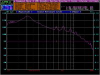
Below is a LMS sweep of my JBL2342 Bi-Radial Horn with a JBL2425. Plot is raw, no smoothing applied. No crossover.
Are those peaks from 5.5kHz upwards the ripples/internal reflections you're referring to?
Attachments
About the JBL horn, I don't recall the HF peaks being that strong, but they could be, I suppose. Look for corresponding blips in the impedance curve. Discontinuities will show up there, as will standing wave modes (down low) and diaphragm breakup (up high).
As for measurements of my speakers, they are on the "Measurements Datasets" link on the first page of this thread. There's a whole lot of other stuff on that page as well.
As for measurements of my speakers, they are on the "Measurements Datasets" link on the first page of this thread. There's a whole lot of other stuff on that page as well.
The graph that "just a guy" posted is over a 110db window and does not say if smoothing was applied. Sure, everything will look smooth. I'm not arguing for or against anybody. Jeff B. is someone who is very knowledgeable and a great designer whose designs speak for themselves. Just that, that particular graph doesn't show anything, except evenness of off-axis response.
Wayne, when you say ripple, could you say exactly where the ripples are? I was under the impression that the ripples are in the low end of the response. And they are not 5db tall. The H290C is better, slightly. To me, the bigger advantage is the extended response below 1 kHz.
Wayne, when you say ripple, could you say exactly where the ripples are? I was under the impression that the ripples are in the low end of the response. And they are not 5db tall. The H290C is better, slightly. To me, the bigger advantage is the extended response below 1 kHz.
I agree with you on the measurements. It's apples and oranges unless we use the same measurement systems, or at least similar. We also need to be sure the presentation is the same - same resolution, same smoothing and same scaling.
As for comparison/interpretation of the response charts, as long as the data is measured and presented equally, I'd prefer to leave interpretation to the reader. Because you're right, it isn't 5dB everywhere.
Anyone can see the differences in sensitivity, ripple and distortion. It is what it is.
As for comparison/interpretation of the response charts, as long as the data is measured and presented equally, I'd prefer to leave interpretation to the reader. Because you're right, it isn't 5dB everywhere.
Anyone can see the differences in sensitivity, ripple and distortion. It is what it is.
The room and controlling reflections in a small room is the issue, as pointed out earlier the ceiling, floor and sidewall reflections are issues here, ideally if one controls the first reflections so they are >= 10ms and they reflections are reduced in amplitude a lot of 'problems with speakers disappear.
This seems to me to be one advantage of a well designed floor speaker. Another example is an electrostat, which can have a controlled dispersion as long as it isn't placed closer that 4 ft from a wall.
a full range corner horn à la Mr Parham is another example, this cannot be denied
there are many ways of addressing the same issue
for example Stu Hegeman's approach to loudspeaker design evolved from full range corner horn concept to an up-firing horizontally constant directivity concept

An externally hosted image should be here but it was not working when we last tested it.
Last edited:
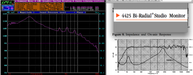
Your sweep looks like the ripple is less than JBL's measurement (the 4425 monitor uses the 2342) with crossover, about 3 dB peaks compared to +/- 3 dB.Below is a LMS sweep of my JBL2342 Bi-Radial Horn with a JBL2425. Plot is raw, no smoothing applied. No crossover.
Are those peaks from 5.5kHz upwards the ripples/internal reflections you're referring to?
For what it's worth, I have also included a pair of plywood horns using JBL 2420 drivers with titanium diaphragms (similar to the 2425), the 9045A is an asymmetrical vertical dispersion conical 90 x45 degree horn with a smooth transition throat similar to the Hughes quadratic throat.
The other is a dual driver diffraction horn similar in concept, but much smaller than to the old Altec Manta Ray horn.
Frequency resolution is 1.5 Hz, no smoothing applied, raw on axis response.
The diffraction horn appears to have slightly less ripple than the 9045A, yet the 9045A "sounds" smoother.
Art
Attachments
Yes, you're probably right. I used the JBL 2370 for a while, a couple decades ago. So I'm more familar with it. It had 3-5dB ripple from various causes, both lower and higher modes.
Higher modes at 5kHz, 6.5kHz and 8kHz appear in the impedance curve as well as in the response curve. They show up as little blips in the impedance curve that match the ripple in the response curve - A dead giveaway that it is the result of a discontinuity, the diffraction slot in the throat.
The lower modes are around 500Hz and 1kHz, with a third appearing around 2.2kHz. Those are mouth reflections, typical standing wave modes that all horns have down low to some degree or another.
And of course, there's usually a little blip or two way up high, above 10kHz. That's diaphragm breakup.
I agree with you on the measurements. It's apples and oranges unless we use the same measurement systems, or at least similar. We also need to be sure the presentation is the same - same resolution, same smoothing and same scaling.
As for comparison/interpretation of the response charts, as long as the data is measured and presented equally, I'd prefer to leave interpretation to the reader. Because you're right, it isn't 5dB everywhere.
Strange that you say that. Because all the SEOS™ bashing you did on other forums was using your own horn measurement along side a chart that you knew was done by someone that clearly said he had never taken measurements before or used the equipment. Then later he realized his charts were incorrect. But of course, you kept using them after you knew were incorrect. Interesting.
Wayne, many here probably don't know that you've been bashing the SEOS ever since it was designed by forum members and the DIY community. First you said the SEOS wasn't as good because it wasn't "catenary", then others said it was. Then you changed the story and said it wasn't as good because it didn't have better constant directivity. But when others showed how good it was.....oh no, you have to think of something else......you then change and say 'constant directivity doesn't really matter.....it's all about "uniform" directivity.' Well of course. 🙄
If we start comparing the dreaded horn honk on other horns, my guess is that your information will then be about why horn honk......could be a good thing, as long as it's 'uniform honking'.

***********************
We rarely see companies do everything in their power to try and discredit the "competition" like you do on a regular basis. Yet people might forget WHY you've been doing it. It's not to get to the bottom of anything. It's so you can make more money by trashing the other guy. Yet I've never put down your stuff at all, but you just keep it up......to make money.
Let's not forget that this is no different than any other company trashing the next guy with bogus info. You have a company that made a horn. You see the DIY Community design something really neat, actually come together and get it produced, get great speakers designed......and you immediately start trashing every part of it. But the other guy just sits there and let's it happen.
Why do you feel the need to use bogus information and charts and continue to discredit others? Bottom line......money.
***********************
Wayne, you make good speakers like many other companies. No one has ever said otherwise. But why discredit others on a regular basis? Why not JBL or FaitalPro? Why is it that over the past year it's all been directed towards one really nice SEOS waveguide? Pretty obvious but kind of sad.
Last edited:
I would take a horn that has the most uniform/constant directivity as low as possible (for a given size) over flat frequency response. There are 3 critical items I look for.
1. Uniform/constant directivity in the passband.
2. Directivity at the low end.
3. Smooth frequency response at the low end.
In that order. 1. is obvious and a must. 2. is about "how low can I push this thing". And 3. is about, "how easy will it be to integrate with a woofer".
If the FR is up and down through the pass band, I don't care. I'll just eq it into shape IF it's uniform off axis. If I wanted a device that had flat frequency response, smooth impedance, easy to work with, etc. I'd go with a dome in a waveguide. Which I sometimes do. Usually a simple cap + resistor will snap it into place really easy and dead flat. But this is DIY, I'll add parts like Geddes until its a pancake.
As for my opinion of SEOS vs H290C, well, I haven't used the H290C so I'll leave it at that.
Wayne, where did you get the measurement posted in your OP? It looks like MTG90s measurement. Are you using that?
(EDIT nevermind, I found the old post. Which doesn't show quite a much gain as your measurement shows, especially on the low end - http://www.avsforum.com/t/1469042/4-pi-vs-diy-sound-groups-fusion-sentinel-15/120#post_23238756 )
Also, it doesn't totally match measurements of your waveguide I've seen elsewhere, where there's a peak/dip combo down around 1khz. Can you explain that?
Last edited:
Wayne,
I also had a really neat idea that you might be interested in if you could bury the hatchet.
The SEOS™ has great constant directivity, proper throat angle, controls horn honk, etc. But if you think the DIY Community should also have something else that's different, maybe we could all design it and get it produced like the community did before?
The SEOS got very high marks and while many wanted the 10" and 15" wide model, after we all took votes, most agreed the SEOS-12 would be good for most people. But the demand for other sizes has been pretty high. And it does make some sense because if you're going to make a speaker wide enough for a 15" woofer, why not pair it with a really nice 15" waveguide? So there's a group buy/preorder going on right now for the SEOS-15. I'm just helping to coordinate it right now.
Anyway, the break even cost on the SEOS-12 was $28 after packaging material and Paypal fees. I packaged them up myself in my spare time. No big deal. But had we done 2 models, shipping could have been divided out by more pieces.....lowering the overall cost for everyone.
So here's the idea: You think we also need a uniform horn. I'm not sure of the benefit, but maybe some do and you could explain it. So we prototype a horn that you think has perfect 'uniform' directivity and get it made at the same time as the SEOS-15 or SEOS-10! That's great because it would allow for a well priced model that you believe is the best of the best. No more debates because we could get speakers designed around both models!
I can get the CNC company in Kentucky to make up the baffles and flat packs to match the new waveguide and speakerslike I did with the SEOS and EOS models. I don't mind helping any way that I can.
What do you think?
Last edited:
- Status
- Not open for further replies.
- Home
- Loudspeakers
- Multi-Way
- Uniform Directivity - How important is it?