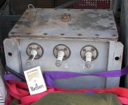
Found recently is a badly stripped Unholtz-Dickie 'shaker' amplifier. I am told by the strippers that it had a pair of 4-1000's. It ran on 3-phase power and used six 866's and two smaller MV rectifiers. It also used four EL34's as drivers. One person said the drive was to the 4-1000 screen grids from the EL34's.
Unfortunately the only components left are the chassis a massive vetical frame, the front and back covers (also cover the sides), the precious output transformer, and the 4-1000 tubes.
All the rest, the wiring, other iron, other tubes, a "phenolic circuit board" as said by the stripper, the tubes sockets were on, the 4-1000 sockets, the meter panel, etc are gone. Probably never to be seen again.
All is not lost. With the OPT in good cond., the 4-1000's,which I am familiar with for RF, and a donated plate transformer of 7500VCT @ 3.75KVA, I think this can be put back together so it looks nice and works fine.
Because so much is missing,it will be like the six million dollar man.. I would like to make it as much like the original in performance as possible.
There is an Unholtz-Dickie amp with 4-400's featured on youtube. I think this one is basically the same.
So, why not try to put it back in operation with new insides. It would look nice on casters in my living room.
So the begging goes out for the manual or schematic for one of these. Unfortunately there's no nameplate, so I can't even name the model.
I've done a resurrection like this before, but on a home-made 1KW AM transmitter found in a scrap yard. The reason I want a schematic is to better see how the drive was done.
Thank you!
PJ
Attachments


Last edited:
That is NOT an output transformer, sorry.
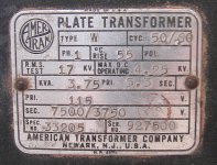
It is the power transformer. The word "plate" has to do with the fact that it is for the plate power.
I'm afraid you just got a box of iron and some copper.
GoatGuy
It is the power transformer. The word "plate" has to do with the fact that it is for the plate power.
I'm afraid you just got a box of iron and some copper.
GoatGuy
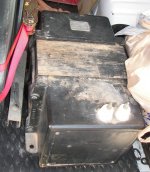
That's incorrect. You have glanced at the Amertrans plate transformer nameplate. If you look at it for real then you will see it is on a black thing, which is obviously the Amertrans plate transformer, which is the only big black thing in the other picture beside the cabinet.
The big gray thing is the OPT and the three white terminals are plate-HV-plate. If I took time to find the video this would be obvious as it is what's connected to the output tube anodes. The video may be linked from an amfone.net topic not sure where I saw it.
You are right about one thing, I did just get a box of iron and some copper. Its exciting.
Just going by what the nameplate says then I'd be inclined to call it a power transformer. 115 Volt primary 50/60 Hz doesn't sound like an output transformer!
That's a serious single-phase HV power transformer for starters -I hope you've got a good mains incomer with a bit of inrush suppression!
Is the OT oil filled? Or should I say 'was' the OT oil filled 🙂
Have you got a suitable HV tester to check the insulation - omg, the practicalities of a renovation just keep getting harder and harder .....
Is the OT oil filled? Or should I say 'was' the OT oil filled 🙂
Have you got a suitable HV tester to check the insulation - omg, the practicalities of a renovation just keep getting harder and harder .....
The nameplate is for the power transformer.
The output transformer was oil filled but it was drained and will be refilled with modern transformer 'oil'. I prefer to wait until it has oil in it again and has been warmd up a little to work the oil in before trying any hipot tests.
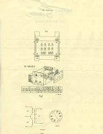
This site has a Philips-made amp, similar but a smaller one:
EL6471 1kW Großverstärker (Type 102408)
It looks like Philips and Unholtz-Dickie made the same design, perhaps for different regions as this one is from the USA.
Looking at the chassis for the Philips, it is about 60% the height of this one here and the OPT covers only 2/3 of the rear of the chassis. The one here covers the full width, so I would assume it is a little more powerful. It looks like the original mains transformer for mine is supposed to be mounted horizontally across the back of the frame near the bottom.
I may have a 3-phase mains transformer to fit it, although I gave it away I can get it back. It may also be possible to use a smaller plate transformer than the substitute I was given, which is from a WWII military transmitter. It would have to go on a 30A circuit, but the way I see it, if this can be made to work again, the electrician cost won't seem too much.
Unholtz Dickie has an office in California. Possibly they might help if I can find the model number of this thing on the chassis somewhere.
The output transformer was oil filled but it was drained and will be refilled with modern transformer 'oil'. I prefer to wait until it has oil in it again and has been warmd up a little to work the oil in before trying any hipot tests.
This site has a Philips-made amp, similar but a smaller one:
EL6471 1kW Großverstärker (Type 102408)
It looks like Philips and Unholtz-Dickie made the same design, perhaps for different regions as this one is from the USA.
Looking at the chassis for the Philips, it is about 60% the height of this one here and the OPT covers only 2/3 of the rear of the chassis. The one here covers the full width, so I would assume it is a little more powerful. It looks like the original mains transformer for mine is supposed to be mounted horizontally across the back of the frame near the bottom.
I may have a 3-phase mains transformer to fit it, although I gave it away I can get it back. It may also be possible to use a smaller plate transformer than the substitute I was given, which is from a WWII military transmitter. It would have to go on a 30A circuit, but the way I see it, if this can be made to work again, the electrician cost won't seem too much.
Unholtz Dickie has an office in California. Possibly they might help if I can find the model number of this thing on the chassis somewhere.
Top stuff - that link shows the layout beautifully.
Yes, you'd need an industrial connection to just run 1ph, plus then have extra filtering hassles. I guess you could use a separate enclosure for 'modern' bits like circuit breaker and phase-fail relay, to keep the original 'patina' of an old build.
Do you have any idea of the frequency range of the older vibration tables, and the impedance of a drive winding, and whether it was just one axis output or did they use three separate windings and how that was managed?
Are the plate and ht bushings on the OT still ok?
Man, that is some serious iron.
Good luck with your project, and keep us posted.
I expect this will stretch out a while.
Good luck with your project, and keep us posted.
I expect this will stretch out a while.
As far as I know the old shakers went quite low, maybe to 10Hz. It would depend on how much power was needed, right? I guess the things came with a spec sheet describing the operating conditions.
The voice coil connections are unknown. There are some 14 connections for that side. It's my expectation that some combination will match some sort of speaker.
All the HV bushings are fine. I have no idea how many axis and guess just one. From what I understand about some old shakers, there could be another cabinet full of reactances to shift the phase of the output signal so that application to two axes might make an elliptical motion, but none of that is clear just speculation. I have stripped some ex-military shaker drive matching cabinets found at Goban Supply in Chicago. They were full of 13KVA variacs, banks and banks of 440V and 600V oil caps, and giant rheostats.
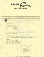
I took some info from the Unholtz Dickie amplifier.
Type 129040
Nr. 639
Original tube compliment:
output tubes QB5/1750 (x2) (someone subbed 4-1000A's)
driver tubes EL34 (x4)
HV rectifiers RG3/250A (x6) (someone subbed 866's)
The voice coil connections are unknown. There are some 14 connections for that side. It's my expectation that some combination will match some sort of speaker.
All the HV bushings are fine. I have no idea how many axis and guess just one. From what I understand about some old shakers, there could be another cabinet full of reactances to shift the phase of the output signal so that application to two axes might make an elliptical motion, but none of that is clear just speculation. I have stripped some ex-military shaker drive matching cabinets found at Goban Supply in Chicago. They were full of 13KVA variacs, banks and banks of 440V and 600V oil caps, and giant rheostats.
I took some info from the Unholtz Dickie amplifier.
Type 129040
Nr. 639
Original tube compliment:
output tubes QB5/1750 (x2) (someone subbed 4-1000A's)
driver tubes EL34 (x4)
HV rectifiers RG3/250A (x6) (someone subbed 866's)
Screen grid modulation was used as an inexpensive way of getting high power a.m. You didn't need the expensive modulation transformer.
The voice coil connections are unknown. There are some 14 connections for that side. It's my expectation that some combination will match some sort of speaker.
I think you mean 'will match some stack of high powered speakers' 😀
My interest in frequency response was actually more bent towards high frequency range, but yes the inductance would need to be large enough to match the low end. You could at least test inductance and turns ratios without oiling, and hopefully find some comparable PP impedance values for that tube to give you an idea.
Reminds me of when Cerwin Vega brought out a new range of cinema speakers for the movie Earthquake back in the early 70's. Now I know what amp they used 😱
Earthquake - I read somewhere that there was a special LF noise generator controlled by film tracks and that several rows of seats had to be removed in the rear of some smaller theaters for the giant speakers. I don't know what is true.
"some stack of high powered speakers" is right. I've been looking at 18" and even some much larger cones.
There are always issues and one of mine seems to be space as my living room is maybe 12x15. There's room for a couple racks and a large pair of full range speakers at one end with a TV or projector screen in the middle.
It's not clear where 4 or more 18" or 30" woofers could be mounted with enough volume behind them to work. Such speakers also seem to be large only for power handling and have free air resonance of 25Hz and up. They also vary widely in sensitivity. I know only a little about speakers and don't really know what to build. An example is what I have now, 15" Eminence woofers in some 24x18x48" sealed enclosures (10.9 cu ft inside, minus 1 cu. ft. for the internal midrange box, for 9.9 cu. ft.). The boxes are too big for the woofers and when we get to 25Hz they seem to get unloaded and can bottom out. How to get some output there? speaker design is crazy stuff. Maybe a 15" or 18" in the front and another in the rear of those cabinets. Or consign those cabs as-is to the rear channels and start anew for front and a sub. A 50" screen could sit on top of a sub if it were as big as furniture.
Checking the living room I found the old 240V 25A outlet previously used by a 2 ton window unit used before central HVAC was installed. There we go for 4KVA. There are plate transformers at home with 240V input as well.
The goal is to get to the low note on the organ, 16hz, and also do a good job on the live cannon of the 1812 overture. The room may be too small to really 'hear' that but it could be felt, I think.
I bought a copy of the "loudspeaker design cookbook 7th edition". I shouldbe able to learn something more from that, but no speaker book I've ever read included everything there is to know.
OK, so it sounds like you're serious about matching the amp to speakers! And you're application really is just 'subwoofer' due to the mono channel.
diysubwoofers.org has always been a great repository of design and practical info.
I guess the first practical step is really to work through on the output impedance range that can be configured for the valve/OT/topology combination.
Maybe also look for an industrial strength linear actuator on ebay to couple to your floor-joists 🙂
Ciao, Tim
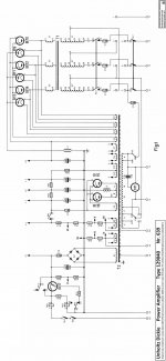
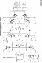
Earth shaker? could be a house shaker.. but "only" 2KVA.. I hope I can earn that respect once this amp is rebuilt. It will stretch out a while, yes. From the document sent to me here are the individual pages as the whole thing was too big for the rules here. The schematic is in two pieces as it was too large.
Anyway, the tube types are at the 'bottom' of the power supply page. The output tubes in this one were subbed to 4-1000's. The originals are better requiring a simple blower, but maybe not easy to find any more. EL34's are easy. 866's are easy. The input tubes are I think similar to 6BQ5. The voltages shown are likely signal voltages.
I have to ask philips for the full manual, sorry I can't know the DC voltages in there. i am guessing 3KV for the HV side and 500-600V on the drivers. They are cathode follower, perhaps this was class AB2.
Anyway, enjoy looking at this schematic! It will take some study to see all the things going on in there. Keep in mind it was not always expecting a perfectly matched load either.
Attachments

Are you saying the data in that service sheet is what you have in your amp, as T1 is 3ph mains input ??
Neat territory. Like venturing into deep space to me. It got me to wondering , so I looked. Did you know that Unholz-Dickie is still in business? Maybe they have archives . Shaker Systems - Unholtz-Dickie Vibration Test Equipment
At one time in its past, it had a 3-phase power transformer.
What is now present is only a skeleton:
the stripped chassis with front and back covers, and the big gray OPT.
Everything else is gone.
Another guy has the amp's 'control panel' and will send that to me, and the guy I got this chassis and OPT from also gave me a single phase 3.5KVA plate transformer as well as a pair of 4-1000A's.
\\\\\
There was a lot of trading done for this. I gave up:
----
Bogen MO-200 amp
Bogen MO-200 Specifications
already split in two and cathode feedback added like these:
The Shrine of the Ancient and Most Excellent RCA MI-12188A Power Amplifier
The Shrine of the Ancient and Most Excellent Stromberg-carlson APH-1050 Power Amplifier
The Shrine of the Ancient and Most Excellent Stromberg-Carlson AP-55 / AP-56 Power Amplifier
----
Tektronix dual trace 50MHz scope
-----
a new 3-1000Z
-----
Garmin GPS II (good as it has an old fashioned NMEA data serial port)
\\\\\
A fair trade everyone was happy with.
#####
I will enjoy that schematic and article very much!
6 bottles rectifier indeed! (plus the two smaller ones are also mercury)
However, single phase will make this only two rectifiers but higher current requirement for each.
A pair of 872 (or 8008) mercury rectifiers would be the minimum for this amp. They are rated the same voltage as 866's but 1.25A current each, so as compared to the 866 rating of 250mA they are the next step up.
The next bigger rect. (for those with an interest) are 575A's (or 673). These would be overkill, each rated 1.75A.
I use four 673's in an old home-built ham radio transmitter having two 3000V/1A power supplies. It's mucho overkill for ham use but that is what the guy built. I can only say it takes a -lot- of power to get a big glow in those.
####
I have more on this as I've been doing some power supply simulation but I have to go to church and will be back after while. I would sure like some opinions on the power supply ideas.
Attachments
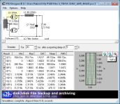
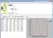
Here's what there should be for power if that previously mentioned transformer is used. This also uses other parts on hand.
7500VAC 3.75KVA transformer
Two 8uF 5KV oil caps in parallel
Two 8H 400mA chokes in parallel
3245V @ 1.1A and 3% ripple.
The second file is for three of those 400mA chokes in parallel.
The tube data shows 1.2A max., so it's better to not overload the inductors.
7500VAC 3.75KVA transformer
Two 8uF 5KV oil caps in parallel
Three 8H 400mA chokes in parallel
3323V @ 1.07A and 5.7% ripple. too much?
7500VAC 3.75KVA transformer
Two 8uF 5KV oil caps in parallel
Two 8H 400mA chokes in parallel
3245V @ 1.1A and 3% ripple.
The second file is for three of those 400mA chokes in parallel.
The tube data shows 1.2A max., so it's better to not overload the inductors.
7500VAC 3.75KVA transformer
Two 8uF 5KV oil caps in parallel
Three 8H 400mA chokes in parallel
3323V @ 1.07A and 5.7% ripple. too much?
Attachments
Last edited:
- Status
- Not open for further replies.
- Home
- Amplifiers
- Tubes / Valves
- Unholtz-Dickie amp, 4-1000's