Why do you want to ground the centre taps at all? A balancing transformer should have no ground connection on its secondary, otherwise it's not guarenteed to be balanced. And in this case there is no need to ground the primary centre tap either. Some sort of secondary load is a good idea, and often it is a Zobel network.
thanks Merlinb.....
if i may stretch it further, a simple cathode follower is better imho...
a cap to block dc going to the primary coils is good for inductance..
Yes, a cathode follower would give superior performance to a cathodyne. The main difference is the necessary gid voltage, so the choice depends on how you want to arrange your DC coupling.
I just took a peak at this thread and see that I missed some great answers. Thanks for the additional info.
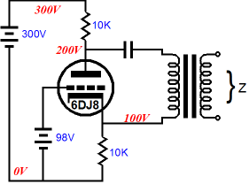
My thinking for the cathodyne or split-load inverter before the OPT was to use the tube for phase splitting, then use the OPT as a simple 4:1 for driving a balanced line to the power amp inputs. The stage preceding the cathodyne would provide the gain, the cathodyne does the phase splitting and the transformer drops the output Z (lowers voltage and raises current).
With the OPT run with no DC current on the primary, it should work like a parafeed transformer, but would not need to do the phase splitting. I've heard tell that using transformers to split phase can be problematic. Why, I don't know. It could be totally wrong. This cathodyne to PP-parafeed idea popped into my head, and I'm wondering if it has any merit.
More to the point, I've been running my simple 6N30P common-cathode linestage into the Edcor WSM15K:15K clipped into the input of my power amp. I found this page and it looked appropriate for what I'm doing:
(Sample)RLC Low-pass Filter Design Tool - Result -
It's got Rseries, Cseries and Lparallel. I made Rseries equal the Zout of the linestage tube (I figure about 1300 ohms for 6N30P run at 20mA Ip), Cseries was 3uF (that's the output cap on the linestage). Lparallel is the primary inductance of the WSM15K:15K, which measures at 15H.
I plugged in those values and got quite a surprise. It says the F3 is 23.7Hz. (I thought it sounded light in the bass...) Worse, it says the Q of the resulting filter is high, at 1.72.
I increased the Cseries to 9.1uF -- actually two 2.2uF ERO MKP's in parallel with a 4.7uF ERO mylar wound cap. (That's what I had around that will fit in the chassis.) That dropped the F3 to 13.7Hz, but the Q of the filter only went down a little, to about 1.
I tried reducing the Rseries (rp of the linestage tube) to 800 ohms, but the Q went way higher, up to 1.6. Next, I increased the Rseries to 2.2k, which I figure is about the rp of a 6N6P. That reduced the Q of the filter to 0.58. Pretty close to perfect, no?
The funny thing is that through all this, only the Cseries and Lparallel dictate the F3. The Rseries dictates the filter Q.
Am I using that online calculator in a valid way? I think it's a simplified model of a triode running into an idealized OPT. But of course, I've been wrong many times before.
Here's the current circuit (attached). It's just an experiment at this point.
--
Attachments
did you look at SY's Impasse preamp?
Mr. Yaniger's preamp for the Pass F4 was unbal in bal out (You can eliminate the input transformer)
An externally hosted image should be here but it was not working when we last tested it.
Yup, I have looked at the ImPasse, and plan on building one. It sure would be simpler than messing with transformers. I intend to compare 'active balanced' vs. transformer balanced.
With a gain of about 20x, the ImPasse as designed will have too much gain. To the best of my limited understanding, C2 in the ImPasse schematic passes the AC signal from V1's plate to V2's grid, while R8 and R9 form a voltage divider, putting the grid of V2 at about 120V. (Incidentally, R19, which is supposed to be a grid stopper, is in the wrong place in that schematic.) If I take away C2, will that allow R8 and R9 to act as a voltage divider for AC signal too? That might be a way for me to knock the gain down a little.
I need about 4V peak at the power amp grids to drive the amp to clipping. I figure I want the input sensitivity at the preamp to be no lower than 500mV peak. So I need no more than about 8x gain from the preamp. (Isn't that always the problem?)
A transformer with 2:1 step-down does that. 4:1 would work fine too. That was one reason for the transformer idea. The biggest problem with transformer coupling is the expense of decent iron. The other problems are getting the loading right so the highs sound relaxed, and finding the right combination of primary inductance and parallel-feed capacitance (couple cap from the voltage amp stage).
So I bought a couple of Edcor line level coupling transformers to play with. I'm clip leading in and out between the WSM15K-15K, XSM10K-600 and transformerless (unbalanced to the power amps). So far, I'm getting best results from the 15k:15k with 10k load resistors on the secondary, each end to CT. (The gain's still too high, though.)
Right now I have the XSM10K-600 in as a 4:1 stepdown on the input of the power amp. I'm getting just the right gain from the line stage into the power amp this way. The transformers added a hard edge to the sound used with 10k secondary load resistors, but 1k seems to make the sound smooth. (That's 1k from each end of the secondary to CT, in parallel with the 100k grid leak resistors in the power amp, for an effective load of 909R-CT-909R.) I need to figure out what to do for a signal generator and 'scope. You can't get a nice sharp 1kHz square wave from a CD player, can you?
--
I would question the usefulness of that Impasse design. The whole point of balanced signals is CMRR, which requires equal diriving impedances. But the cathodyne has grossly unequal driving impedances, so that circuit will give poor CMRR, in which case, what's the point of the balanced output? Maybe there's a good answer I'm missing since I haven't bothered to read up on the circuit (in which case, sorry SY!).
I have generally found that heavy loading down to about 1K gives the best response from these transformers. You can refine it by working out an equivalent Zobel which will unburden the preamp tube somewhat.
I still think a simple Mu-Follower with the output taken from the cathode of the top triode will give the best results from a simple build. I have also found that a cap in the 10uf range will generally work adequately.
Shoog
I still think a simple Mu-Follower with the output taken from the cathode of the top triode will give the best results from a simple build. I have also found that a cap in the 10uf range will generally work adequately.
Shoog
That may give him more gain than he needs, forcing the gain to be dependent mainly on valve choice rather than circuit design. An ordinary gain stage and cathode follower would allow rather greater flexibility in choosing the gain of the first stage.I still think a simple Mu-Follower with the output taken from the cathode of the top triode will give the best results from a simple build. I have also found that a cap in the 10uf range will generally work adequately.
I have a personal preference against cathode followers (I prefer SLCF's), but I get where you are coming from.
Something like the 12B4-A might make a good candidate, but it is only a single triode per bulb.
Shoog
Something like the 12B4-A might make a good candidate, but it is only a single triode per bulb.
Shoog
Shoog:
I have generally found that heavy loading down to about 1K gives the best response from these transformers. You can refine it by working out an equivalent Zobel which will unburden the preamp tube somewhat.
Do you mean 1k loads on the secondary winding? If so, I can easily try that. Also, are you thinking that would be for the 4:1 transformer, or for the 1:1?
I think that the 4:1 transformer looks like a good solution, since it will drop gain 4x. So if I use say a 6DJ8 with 25x gain, that leaves me with about 6x gain. Perfect.
If I use the 1:1 transformer, then it's more complicated. I was thinking of trying some triode wired 6P43P-EV I have. The Klausmobile site shows it as being very linear.
I was getting a very pleasing sound with the 1:1 (15k:15k) transformers as in the drawing I posted, but with 2.2uF coupling caps from the 6N6P plates (two paralleled 1uF Vitamin Q caps). Unfortunately, the bass was rolled off. Doing some calculating (and not sure if I'm doing it right), I thought that increasing the output caps to 9uF would bring the bass back, and with decent damping. The only way I could get that 9uF was to parallel two 2.2uF 400V ERO MKP caps together with an ERO 4.7uF 450V mystery film cap. Now the bass is good, but the highs are too sharp and zingy. I'm not sure if that's due to the 'sound' of those caps in that place in the circuit, or if it's high frequency ringing from the transformers. I've tried load resistors down to 10k. Should I try something drastic like 1k?
Merlinb:
The whole point of balanced signals is CMRR, which requires equal diriving impedances. But the cathodyne has grossly unequal driving impedances, so that circuit will give poor CMRR,
Oh no, not this again...
To the best of my limited understanding, the cathodyne only has unequal source impedances if driving dissimilar load impedances. If the load impedances are equal (as they will be in this case, due to driving a class A PP stage) then the cathodyne presents an equal source impedance from its plate and cathode. It will require a well-filtered power supply, but I still think it's a viable option.
I'm keeping an open mind, but my bank account's telling me that I won't be able to buy the best transformers for the job...
--
Which, when an extranal hum field is impinging on one of its outputs, is exactly what happens! 😛 It's the extrnal hum fields that need to see equal source impedances, not the audio signal.To the best of my limited understanding, the cathodyne only has unequal source impedances if driving dissimilar load impedances.
(Works fine with a transformer output, of course, since that is floating).
EDIT: Ah, apparently SY was using it purely to drive a balanced power buffer (large signals), so the design does not care about losing the hum-cancelling effects of proper balanced signal transmission.
Last edited:
Do you mean 1k loads on the secondary winding? If so, I can easily try that. Also, are you thinking that would be for the 4:1 transformer, or for the 1:1?
I have found that a resistor of 1k across the whole secondary can work. I like to put in that value and then increase it in stages listening at each stage to see when it turns "nasty". You will find that the nastiness corresponds to a drooping frequency response from about 30K-60k with then a sharp rise at 60k followed by an abrupt tail off. You will also see overshoot on the waveform - and possibly ringing. So when you get the sound you like its then time to see if you have tamed this response curve with a scope.
Do not trust a sound card as a test signal because they will often have significant high frequency attenuation and so will not reflect the real behaviour of the transformer. A real SINE wave signal generator is essential for testing.
I would agree with this.I think that the 4:1 transformer looks like a good solution, since it will drop gain 4x. So if I use say a 6DJ8 with 25x gain, that leaves me with about 6x gain. Perfect.
If I use the 1:1 transformer, then it's more complicated. I was thinking of trying some triode wired 6P43P-EV I have. The Klausmobile site shows it as being very linear.
I was getting a very pleasing sound with the 1:1 (15k:15k) transformers as in the drawing I posted, but with 2.2uF coupling caps from the 6N6P plates (two paralleled 1uF Vitamin Q caps). Unfortunately, the bass was rolled off. Doing some calculating (and not sure if I'm doing it right), I thought that increasing the output caps to 9uF would bring the bass back, and with decent damping. The only way I could get that 9uF was to parallel two 2.2uF 400V ERO MKP caps together with an ERO 4.7uF 450V mystery film cap. Now the bass is good, but the highs are too sharp and zingy. I'm not sure if that's due to the 'sound' of those caps in that place in the circuit, or if it's high frequency ringing from the transformers. I've tried load resistors down to 10k. Should I try something drastic like 1k? --
You may find that you have got resonances between the caps.
Shoog
Last edited:
I'll try the 1k resistor across the whole secondary, and give it a listen.
No time to drill holes this evening, but maybe tomorrow. I think I'll make a line stage with two 9-pin sockets, one per channel. That way I can wire it for two 6DJ8 mu-followers, with a +350V 40mA power supply, and use the 4:1 Edcor transformers on the outputs. If the experiment doesn't work out, I can change it to an ImPasse-style circuit using a 6CG7 into a 6DJ8 cathodyne.
Do you mean resonances caused by paralleling capacitors?
I think I can find 10uF 400VDC motor run (metallized poly-something) caps at a surplus store not too far away. I'll try those instead of the three paralleled caps.
SY also used a 1:1 input transformer and a Maida regulator for the B+.
I'd be using it for 1V input to about 6V output. That's fairly high level for audio signals, isn't it?
--
No time to drill holes this evening, but maybe tomorrow. I think I'll make a line stage with two 9-pin sockets, one per channel. That way I can wire it for two 6DJ8 mu-followers, with a +350V 40mA power supply, and use the 4:1 Edcor transformers on the outputs. If the experiment doesn't work out, I can change it to an ImPasse-style circuit using a 6CG7 into a 6DJ8 cathodyne.
You may find that you have got resonances between the caps.
Shoog
Do you mean resonances caused by paralleling capacitors?
I think I can find 10uF 400VDC motor run (metallized poly-something) caps at a surplus store not too far away. I'll try those instead of the three paralleled caps.
Merlinb:
Ah, apparently SY was using it purely to drive a balanced power buffer (large signals), so the design does not care about losing the hum-cancelling effects of proper balanced signal transmission.
SY also used a 1:1 input transformer and a Maida regulator for the B+.
I'd be using it for 1V input to about 6V output. That's fairly high level for audio signals, isn't it?
--
Last edited:
Large film caps can have inductance which add to the wire inductances which maybe interacting between the different capacitances and inductances. Some people claim that bypassing/paralleling is always worse than a single good quality cap. Its not my experience, but who knows. It could also be that you are simply hearing one of the caps which has a bright top end - mica caps can sound very harsh.
I have had good success with big old paper in oil caps (real vintage ones) with polystyrene bypasses. Very natural to my ears and not at all old-fashion in tone.
Shoog
I have had good success with big old paper in oil caps (real vintage ones) with polystyrene bypasses. Very natural to my ears and not at all old-fashion in tone.
Shoog
Last edited:
I was using four old Vitamin Q caps in the preamp, which I liked in this application. (They make dull sounding coupling caps between driver stage and output stage in a power amp, though.) But at only 1uF each, those Vitamin Q's aren't anywhere near high enough in value for this application. I wonder what would happen if I put those back in, in parallel with something else? I can see this turning into quite a sidetrack...
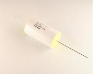
What's in there now are Roederstein (ERO) MKP1841.

I have a pair of ASC NE135 I bought surplus (10uF 440VDC). I have no idea if they're metalized polypropylene or metalized polyester. Maybe those would work better. Picture is attached.
--
What's in there now are Roederstein (ERO) MKP1841.
I have a pair of ASC NE135 I bought surplus (10uF 440VDC). I have no idea if they're metalized polypropylene or metalized polyester. Maybe those would work better. Picture is attached.
--
Attachments
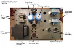
Junkbox Preamp layout?
I took a break from swapping resistors in and out to rummage through my boxes of electronic junk, to see what I could find for making this preamp.
I found a chassis from an old Heathkit W5 power amp. About 20 years ago, a friend of mine had stripped it of its Acrosound OPT, leaving me the carcass.
I scrounged up two 7H 50mA chokes. When you look at the picture, please note their positions relative to the power transformer and to each other. Does anyone know if they will inject hum into each other if positioned like that? Should I mount them one on top of the other, and wire them in anti-phase? Or can I wire them in anti-phase the way they are, and get them to act in humbucking fashion? (I'll have to read up on that...)
I have a Thordarson power transformer, 650VCT 40mA. The one pictured is much larger, 600VCT 120mA. I might go with that one because it lines up with the holes that are in the chassis already, and so it will run cool. I've read that using a power transformer near its VA limits can cause its core to saturate, which can radiate interference all over the place. If I use a much higher rated pwr xfmr than necessary, it should run cool and quiet, right?
I haven't used a tube rectifier in a long time, but I have some 5Y3GT and 5V4GA. Or I can forget it and use UF4007 diodes.
I'm worried about where to place the audio OPTs. The way I have them, they're as far away from the pwr xfmr as I could manage. Their cores aren't at exact right angles to the pwr xfmr core, but they're not parallel either.
I've attached a picture of my proposed layout. Any opinions on a better way to position the various bits and pieces so I don't get hum coupling into the OPTs?
--
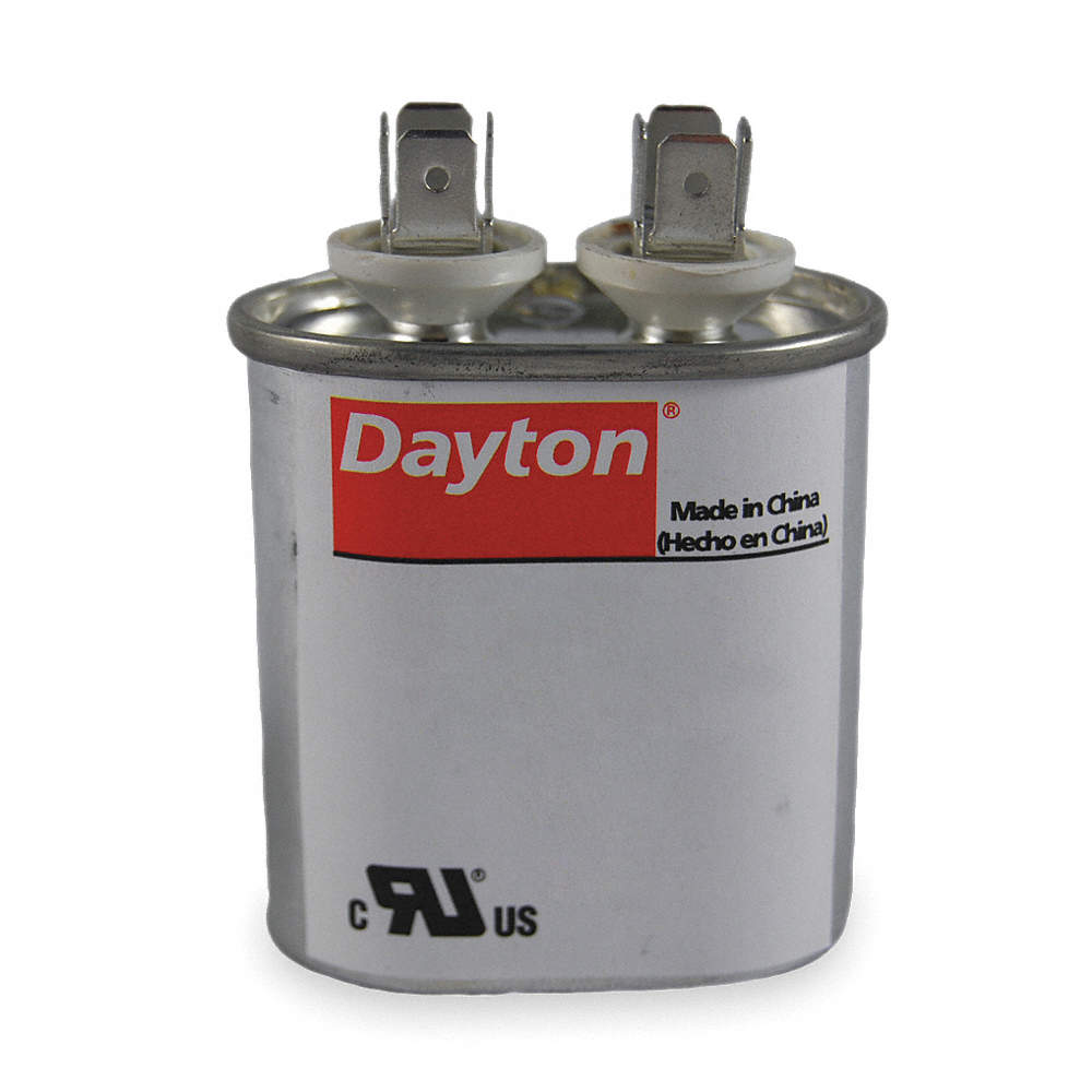
PS - Re: oil caps - Have you tried those oil-filled motor run caps you can get from Grainger, Allied, Parts Express, etc? Something like this:
I took a break from swapping resistors in and out to rummage through my boxes of electronic junk, to see what I could find for making this preamp.
I found a chassis from an old Heathkit W5 power amp. About 20 years ago, a friend of mine had stripped it of its Acrosound OPT, leaving me the carcass.
I scrounged up two 7H 50mA chokes. When you look at the picture, please note their positions relative to the power transformer and to each other. Does anyone know if they will inject hum into each other if positioned like that? Should I mount them one on top of the other, and wire them in anti-phase? Or can I wire them in anti-phase the way they are, and get them to act in humbucking fashion? (I'll have to read up on that...)
I have a Thordarson power transformer, 650VCT 40mA. The one pictured is much larger, 600VCT 120mA. I might go with that one because it lines up with the holes that are in the chassis already, and so it will run cool. I've read that using a power transformer near its VA limits can cause its core to saturate, which can radiate interference all over the place. If I use a much higher rated pwr xfmr than necessary, it should run cool and quiet, right?
I haven't used a tube rectifier in a long time, but I have some 5Y3GT and 5V4GA. Or I can forget it and use UF4007 diodes.
I'm worried about where to place the audio OPTs. The way I have them, they're as far away from the pwr xfmr as I could manage. Their cores aren't at exact right angles to the pwr xfmr core, but they're not parallel either.
I've attached a picture of my proposed layout. Any opinions on a better way to position the various bits and pieces so I don't get hum coupling into the OPTs?
--
PS - Re: oil caps - Have you tried those oil-filled motor run caps you can get from Grainger, Allied, Parts Express, etc? Something like this:
Attachments
Last edited:
Do the headphone test- your setup is ready and waiting!I'm worried about where to place the audio OPTs.
(i.e. temporarily connect power to the PT, and connect headphones to the OT, then just listen for hum while moving the OT around a bit, to find the null.
I wouldn't worry about the chokes, although wiring them in antiphase is certainly an easy way to minimise coupling.
......................... The transformers added a hard edge to the sound used with 10k secondary load resistors, but 1k seems to make the sound smooth. (That's 1k from each end of the secondary to CT, in parallel with the 100k grid leak resistors in the power amp, for an effective load of 909R-CT-909R.)..................................
I have generally found that heavy loading down to about 1K gives the best response from these transformers. ....................
Do you mean 1k loads on the secondary winding?...................... I've tried load resistors down to 10k. Should I try something drastic like 1k?
.....................
I have found that a resistor of 1k across the whole secondary can work...................
What voltage and current would be on/through these 1k resistors?I'll try the 1k resistor across the whole secondary, and give it a listen. ....................................................
I'd be using it for 1V input to about 6V output. That's fairly high level for audio signals, isn't it?
--
What effect will this added load have on the source signal?
Remember the 4:1 are 600ohm line driving transformers. This means they are designed to work into a 600R load, and anything higher is effectively unloading them. Since they are not the best quality - expect this to induce significant resonances if not properly loaded.
1K in parallel with the amplifier input load will still likely be above 600R so it's a good ball park figure to start with.
The load presented to the driver valve is going to be in the region of 10K once impedance transformation is applied so will not unduly load down the driver if selected correctly. Any of the valves suggested will be happy with a 10K load.
I would guess that they chose 600R for studio equipment in the first place because of its relative immunity from resonances at reasonable cost. Amplification is cheap - but good high impedance transformers are not.
I would place the OT where suggested but inside the case if there is space - this will have more benefit overall than increasing the distance between the power supply and the OT.
Shoog
Last edited:
Thanks for the suggestions, everybody.
That's what I was trying to understand from reading RDH4, but it didn't sink in until I read what you wrote. Thanks, that makes total sense now.
That might even apply to a 15k:15k (1:1) transformer running into a 100k load, right? I guess I'd put 15k or 22k across the secondary to load down from the 100k grid leak resistors.
I've been playing with the 15k:15k transformers for the last couple of evenings. Where I'm at right now is that at first the bass response was rolled off, so I decided to increase the value of the preamp's output caps from 3uF to 9uF. The bass response improved, of course. Unfortunately, that changed the tonal qualities of the upper mids and up, for the worse. I think the large value caps are a problem. (Not a surprise.)
I see now how a transformer with a higher primary inductance would make life so much easier. The higher inductance allows the use of smaller value capacitors, which are likely to perform (and sound) better than monster-sized film caps.
I have a handheld LC meter, so I brought it out to measure these xfmrs. (I checked its accuracy by measuring an old Thordarson 16H 50mA power supply choke. That measured almost 17H, so I think the meter is fairly accurate.)
- The Edcor 15k:15k transformers' primary inductance is only about 8H. That was a surprise.
- The Edcor 10k:600 primary inductance measures about 18H. That should be much easier to work with.
Not a problem. Will do.
--
Remember the 4:1 are 600ohm line driving transformers. This means they are designed to work into a 600R load, and anything higher is effectively unloading them. Since they are not the best quality - expect this to induce significant resonances if not properly loaded.
That's what I was trying to understand from reading RDH4, but it didn't sink in until I read what you wrote. Thanks, that makes total sense now.
That might even apply to a 15k:15k (1:1) transformer running into a 100k load, right? I guess I'd put 15k or 22k across the secondary to load down from the 100k grid leak resistors.
I've been playing with the 15k:15k transformers for the last couple of evenings. Where I'm at right now is that at first the bass response was rolled off, so I decided to increase the value of the preamp's output caps from 3uF to 9uF. The bass response improved, of course. Unfortunately, that changed the tonal qualities of the upper mids and up, for the worse. I think the large value caps are a problem. (Not a surprise.)
I see now how a transformer with a higher primary inductance would make life so much easier. The higher inductance allows the use of smaller value capacitors, which are likely to perform (and sound) better than monster-sized film caps.
I have a handheld LC meter, so I brought it out to measure these xfmrs. (I checked its accuracy by measuring an old Thordarson 16H 50mA power supply choke. That measured almost 17H, so I think the meter is fairly accurate.)
- The Edcor 15k:15k transformers' primary inductance is only about 8H. That was a surprise.
- The Edcor 10k:600 primary inductance measures about 18H. That should be much easier to work with.
I would place the OT where suggested but inside the case if there is space - this will have more benefit overall than increasing the distance between the power supply and the OT.
Not a problem. Will do.
--
- Status
- Not open for further replies.
- Home
- Amplifiers
- Tubes / Valves
- Unbalanced In > Balanced Out line amp - How To Do It?