...I have not distortion meter, but signals look good...
I think that your Fluke 125 supports measuring of harmonics content:
An externally hosted image should be here but it was not working when we last tested it.
Last edited:
Yes, but only for industrial frequencies, 40 to 70 Hz as fundamental frecuency (for power measurements with current clamp).
But I can get one FLUKE scopemeter 199C. This oscilloscope can do spectrum analysis of signal on the screen but not with automatic frecuency sweep. It is necessary do manual sweep from generator and save every screen of scopemeter.
But I can get one FLUKE scopemeter 199C. This oscilloscope can do spectrum analysis of signal on the screen but not with automatic frecuency sweep. It is necessary do manual sweep from generator and save every screen of scopemeter.
Zen Mod. I need your permission to show two pertinent schematics from practical simulations using LM317/337 so as not to highjack this thread which is not my intention.
nope
you don't need my permission to post anything
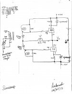
Thanks ZM. The purpose of the attached schematic and this post is to show the scope of its practical circuits which may relate to the PP SIT amp. I do not imply that it is a clone, a replacement etc..for the SIT amp. If anything, it is a close relative to lhquam's Teaser6C which he discussed in the F6 amp thread. The regulators are high transconductance, and voltage variable current sources unlike SIT which is a voltage variable power resistor. Note the following:
- Self bias was used to set the idle current at 300 mA by the 4 Ohm power resistors [1.25V divided by 4]. The regulators did not mind the large bypass cap [10,000 uF] across the self-biasing 4 Ohm resistors because they embody all sorts of protection. SIT or MOSFET may be damaged by the initial high pulse charging current of the cap.
- The upper left hand corner shows the wiring of the 70 Volt Line -10 Watt audio transformer commonly used in PA distribution systems. The 10 W port of the primary was connected to the headphone variable output port of of a CD player [25 mW Pout/ch]. One transformer was used for each regulator; noting that Mr. Pass in the F6 amp thread wrote that 2 identical transformers can be used instead of the current Jensen.
- The 4 Ohm secondary winding was used, and must be loaded as shown with 10 Ohm resistor.
- If desired, local or Pass [like Schade] feedback is introduced by connecting Vo through the loudspeaker to the junction of the 5,700 uF caps. Voltage gain is possibly 8 Ohms of the loudspeaker divided by 2 Ohms which is the parallel equivalent of the 2 secondary impedances of the two transformers.
- One may also connect the loudspeaker from Vo to ground, and use instead a non-inductive resistor as Rf.
- In the case of the SIT amp, the secondary windings are 600 Ohms each. The feedback capacitors will be smaller than shown, and larger valued Rf may be used if needed.
- And it sounds fully satisfactory
Attachments
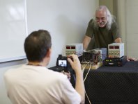
Similar face shape between Mr Pass and PetrusI am preparing an article, but you should feel free to go for it on our own.
The parts are very forgiving, but quiet supplies are a good idea.
😎
Gentlemans feel little cloud of this delicious smell from new Papa article in his topology kitchen ?
Have a nice day
🙂
Attachments


I prepare run in Sony Common Source XFRMR diy amplifier project.
My questions :
It is 2SJ28/2SK82 goes very hot after hours of work ?
Can cooling fan be remplaced by voluminous heat sink alone ? ?
Make more distance between transistors can help ease heat absorbtion ?
What solutions...thanks for Your answers.
Greetings
🙄
My questions :
It is 2SJ28/2SK82 goes very hot after hours of work ?
Can cooling fan be remplaced by voluminous heat sink alone ? ?
Make more distance between transistors can help ease heat absorbtion ?
What solutions...thanks for Your answers.
Greetings
🙄
Last edited:
 On this big photo i see transistors and transformer be close together
it is for keep connections of signal path short ?
What elements be critical in physical positionement of components ?
Last edited:
On this big photo i see transistors and transformer be close together
it is for keep connections of signal path short ?
Not particularly. In playing with these circuits you will find that they
are quite forgiving with regards to lead lengths and such.
😎
What about avoid cool fan and use only heat sinks ?
Nice to have Papa answer on DiyAudio 😀
Thanks a lot Mr Pass
Greetings
🙂
Nice to have Papa answer on DiyAudio 😀
Thanks a lot Mr Pass
Greetings
🙂
Mr Pass be very busy with all recent evenements BAF 2013, Sony CES 2014 and Vfet 40 Years Sony Commemorative Amplifier ,new work space for Pass Labs company and now is cook new wonderful article be coming shortly and with sensational extras like common drain topology amplifier.
" Beast with Thousand of Fets " be master electronic art creation to dream about.In 2014 we have square pleasure DiyAudio members can build amplifiers at much playable cost and discover sit flavor of sound from this upcoming Mr Pass lesson.
Thanks Papa for share extraordinary passion of diy !
Best regards
🙂
Attachments
Last edited:

Nice here's is no cap in signal path i just email Pass Diy about cab.
Best regards
😀
Best regards
😀
Last edited:

Good news tonite.
Worked on the DIY Sony SIT Amp article (part 1) all day today. Maybe finish
tomorrow. Needs one pair 2SK82/2SJ28 per channel.
Time to get your parts from circuitdiy.com.
(Actually at last count they still have lots of pairs, but don't wait too long)

Thanks Mr. Pass for such excellent news !
I admire Your courage and stay in tune
Kind regards
Attachments

Last edited:
Finally article ready for diyers that is fantastic and a big enjoyment
http://www.firstwatt.com/pdf/art_sony_vfet_pt1.pdf
and the new Papa thread 🙂
http://www.diyaudio.com/forums/pass-labs/253411-article-sony-vfets-part-1-a.html
Best regards
Have fun !
http://www.firstwatt.com/pdf/art_sony_vfet_pt1.pdf
and the new Papa thread 🙂
http://www.diyaudio.com/forums/pass-labs/253411-article-sony-vfets-part-1-a.html
Best regards
Have fun !
Attachments
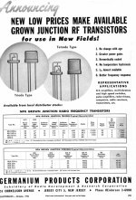
NEC pair
Maybe I'm "ressurecting" an old topic, but it costs nothing to inform DIYA friends about an excellent result based on this project ... 😎
I used a pair of NEC SIT: 2SK70/2SJ20, driven by a custom nanocrystalline toroidal transformer, projected by me. The THD was almost flat 20Hz to beyond 20kHz, not like that there is a transformer in the signal path. The THD of SIT was as expected, but the P channel has less gain than the N channel in this pair, requiring a small attenuation of the N channel, to compensate (or don't attenuate and we will have a mixture of 2H and 3H).
a curious fact is that the P channel has lower rds the N channel (even with same drive for both)! It's usually the reverse ...
They are very robust (if with an good heatsink), surviving various mistakes during assembly and shorts at output.
If someone has that pair, I recommend this project with them! 🙂

- Status
- Not open for further replies.
- Home
- Amplifiers
- Pass Labs
- Ultrasimple SIT PP amp from BAF , or SIT Beast with a Thousand PSUs