it's sort of late at my place now , so I'm even more Dodo then usual
however , not just on your schematic , but also in my latest thinking about biasing mechanismus for SITs - one thing is no-no - introducing any amount of source resistance
their gain/xconductance is too precious ......
however , not just on your schematic , but also in my latest thinking about biasing mechanismus for SITs - one thing is no-no - introducing any amount of source resistance
their gain/xconductance is too precious ......
I've been shuffing very slowly toward doing a "Sleazy Fake" version of this amp using mosfets with feedback. I just nabbed a fairly cheap set of transformers on Ebay (not the Jensens used in the original, but something with similar functionality). The transformers have three separate 150 ohm windings that can be used in a 150:600 ohm step-up/step-down setup, or as a splitter like used in the amp described here. I measured 1.7 Henries of inductance on one of the windings using the inductance bridge here at work, set for 120 Hz excitation frequency. This gives me about 5 mA of excitation current for a 20Hz, 1V drive signal. This doesn't sound like anything beyound the capability of a reasonably hefty input buffer.
How do the Jensens compare? The transformers I have look like they have standard steel lams - the Jensens in Nelson's setup looked like they might have high-nickel lams. But then again, I got two of these transformers for far less than one Jensen - as long as I'm trying to be sleazy, I might as well go all the way...
How do the Jensens compare? The transformers I have look like they have standard steel lams - the Jensens in Nelson's setup looked like they might have high-nickel lams. But then again, I got two of these transformers for far less than one Jensen - as long as I'm trying to be sleazy, I might as well go all the way...
I agree.it's sort of late at my place now , so I'm even more Dodo then usual
however , not just on your schematic , but also in my latest thinking about biasing mechanismus for SITs - one thing is no-no - introducing any amount of source resistance
their gain/xconductance is too precious ......
Nice to see your ideas realized, Antoinel! 🙂
I never would have the idea to use an LM as a SIT fake.....surprise!
😀
I never would have the idea to use an LM as a SIT fake.....surprise!
😀
Thanks generg. The idea of LM use as depletion devices showed up in the F6 thread. This prototype is a demonstrator which may be useful to DIYers who intend to assemble the real PP SIT amp. I have one more post to conclude this endeavour; and to connect the learning with the LSK.. preamplifier that M. Pass showed at BAF2013.Nice to see your ideas realized, Antoinel! 🙂
I never would have the idea to use an LM as a SIT fake.....surprise!
😀
however , not just on your schematic , but also
in my latest thinking about biasing mechanismus for SITs - one thing is
no-no - introducing any amount of source resistance
their gain/xconductance is too precious ......
You want to think about how you are altering the unique load line
characteristics of the part when you add degeneration.
In any case, SITs like the Sony parts have a near-zero temperature
coefficient, so ballast resistors are unnecessary. I have a pair of channels
here using 24 of the Sony parts (per channel) without Source resistors,
and they are totally temperature stable and share nicely when matched.
😎
By Circlomanen in post #727 of F6 amplifier thread. Pls see the thread 'Amplimos 2sk82/28 amp build thread' [by sir5000] in the solid state forum about late August this year. I used LMs to simulate amplimosThanks generg. The idea of LM use as depletion devices showed up in the F6 thread. This prototype is a demonstrator which may be useful to DIYers who intend to assemble the real PP SIT amp. I have one more post to conclude this endeavour; and to connect the learning with the LSK.. preamplifier that M. Pass showed at BAF2013.
Has anyone apart from Nelson built one yet? Would be cool to hear comparisons to the other FW amps & the single ended simple sit =)
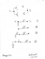
Here is more info gained by the circuit of post #299 which loosely simulates this thread's PP SIT amp. The top part of the attached picture simplifies the original schematic with a particular focus on the power output port [Vo], and the input port of the level shifter [Vi]. Below it are 4 possible feedback and/or connections between these two ports. Here is the value of each for the amp's performace.
- Connection 1. The amp has maximum AC gain. The connection affords a DC servo [feedback]; but no AC feedback.
- Connection 2. The amp has minimum AC gain because the connection affords both full AC and DC feedback.
- Connection 3. The amp has AC gain intermediate between 1 and 2; ~10 as shown. The capacitor still gives full DC srvo.
- Connection 4. It requires shorting across the secondary windings of the transformer. Vi is the input signal port to the power amp with a resulting inverting AC gain of 10.
- Lift the centerpoint of the bias resistors off ground.
- Connect the ouput port to this floating center point.
- Get a circuit like that of Connection 3 less the capacitor. Local AC and DC negative feedback are thus applied to the gates of the cascode FETs to reap its predicted performance benefits.
Attachments
Would the super regulator boards (from the DIYAudioStore) work for the voltage sources in this amp?
Mr.Pass used regulated PSUs as shown by his picture at BAF2013. Still I see in threads several directions to bias SITs. Rothacher regulates the Vgs bias only, audiong uses bias tracking, and juma's psu is another approach. Maybe best to wait for the writeup by Mr. Pass. I am not familiar with the psus from the store to comment.Would the super regulator boards (from the DIYAudioStore) work for the voltage sources in this amp?
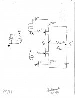
The attached pic shows the concept schematic of the PPSIT amp demonstrated at BAF 2013. The output impedance Zo of output port [Vo] is 4 Ohms when [Vo'] is used as reference ground. What is Zo at [Vo'] when Vo is grounded? Intuitively, no larger than 4 Ohms, and maybe lower than 4 Ohms. I am guessing.
By comparison with this schematic, that of TEASER 6Complementary [F6 amp thread] by lhquam is similar except that he used enhancement MOSFETs. lhquam reported Zo at Vo equal to ~30s Ohms. But what is Zo at Vo'?
By comparison with this schematic, that of TEASER 6Complementary [F6 amp thread] by lhquam is similar except that he used enhancement MOSFETs. lhquam reported Zo at Vo equal to ~30s Ohms. But what is Zo at Vo'?
Attachments
Hello nicoch58. The attached is from today's newspaper the Philadelphia Inquirer. The One and Only is Santa.we hope

Attachments
But what is Zo at Vo'?
Depends on the bias, but looking at my notes, it's about 4 ohms.
😎
Thank you and a have a joyful Christmas.Depends on the bias, but looking at my notes, it's about 4 ohms.
😎
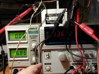
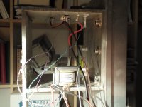
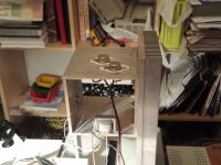
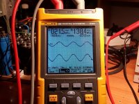
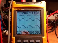
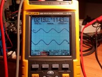
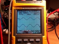
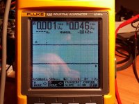
Hello. This is my humble contribution. I have built the amplifier of post 4.
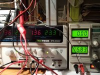
It is very ugly and only one channel. Power supplies are regulated.
I have not any noise at output. Power output is, more or less, 12 watts at 8 ohm. I have not distortion meter, but signals look good...
It is very ugly and only one channel. Power supplies are regulated.
I have not any noise at output. Power output is, more or less, 12 watts at 8 ohm. I have not distortion meter, but signals look good...
Attachments

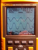
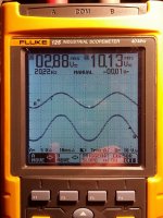
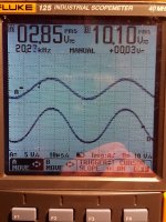
And now the oscilloscope.. Sorry, Trace A is generator and trace B is output to 8 ohm speaker. Other day I will try with music...
Attachments
- Status
- Not open for further replies.
- Home
- Amplifiers
- Pass Labs
- Ultrasimple SIT PP amp from BAF , or SIT Beast with a Thousand PSUs