Hi,
I'm just extremely bored with a our latest "brainstormer"
who has no idea what the word means and in fact has
proceeded on a path which is the extreme opposite.
Espousing faults about something you really don't
know much about is just tedious, especially if
your "fixes" are just cluelessly worse.
rgds, sreten.
Last edited:
Hi,
I'm just extremely bored with a our latest "brainstormer"
who has no idea what the word means and in fact has
proceeded on a path which is the extreme opposite.
Ah, because I took a very simple , direct approach to the problem it isn't "brainstorming" , I get it. It's not complicated or "outside the box" enough.
Espousing faults about something you really don't
know much about is just tedious, especially if
your "fixes" are just cluelessly worse.
rgds, sreten.
How do you know what I know ? I'm clueless because I came to a different conclusion than you did ?
Sure, the 2x4" line array should have better horizontal response through the midband. I agree to that. In EVERY other aspect it is inferior with the drivers suggested.
How is it that you think that a lower efficiency speaker array with very limited max output and a large peak in the lower vocal region is the best option ? Since I'm clueless, I would like you to please explain this to me.
I know the "pitfalls" associated with the speakers that I suggested. They will have less horizontal dispersion through the upper midband than a smaller driver or a smaller driver line array. However, they aren't only to be used for vocals. They are to be used for televised sports events and music.
You're suggestion net result is 86db 1W/1M , a 40wrms power handling ( I would suggest not without a hi pass filter) , a large peak at 200hz , and very limited bass response and max SPL.
I fail to see how this will work in a Pub environment.
Maybe you can enlighten me ?
...........................Blake
After thinking about it a bit more, I have come up with this.
If you were to use them in a line array , with a high pass , strictly using the 2x4" drivers as mid/tweets , with a woofer below (as CZ Eddie suggested earlier) the net result at 12' would be about the same SPL due to the Line arrays better projection into the distance.
The issue now is that you have to come up with a pair of woofers , or a DVC woofer for $12 or so to keep under the $20 limit.
Thanks for contesting my suggestion Sreten , as you made me look at it a bit closer.
So I amend my suggestion. Use the Jamo's (or something higher SPL but similar cost) as mid/tweets for their better horizontal dispersion through the midband , and couple them with a pair of used/cheap woofers to augment the bottom end.
They aren't going to win any SPL contests, but should meet all criteria you brought up.
You'll have to play with hipass frequency and/or damping in the 2x4"s cabinet to get rid of the 200hz peak. According to WinISD those drivers in a sealed cabinet between .25 cu ft and .5cuft show an 8db peak just above 200hz.
According to WinISD the Vas is about 0.023cu.ft. to correlate to an SPL of 83db.
The other issue I see now is you are going to need a lowpass for the woofer or use a bandpass setup as you previously mentioned to roll off the top end of the woofer. I'd recommend a 6th order bandpass to get the most output out of the woofer.
............................Blake
fwiw I had a little 8" driver klam loaded with a Sammi fullrange whose calculated efficiency was ~2% - it was pretty loud at 150 feet distance but was on the verge of thermal meltdown using a 300 watt amp. 20 watts doesn't go very far. It would play reasonably well with the Pioneer B20/BOFU - it would have to be mounted at least to ear height. Up close there were some cavity artifacts so probably not suited for this gig. (damping material in the rear chamber helped some of the reflections IIRC)
An externally hosted image should be here but it was not working when we last tested it.
Last edited:
IDK, so I'm asking , with 4 of the 2x4" drivers in a vertical array, is that enough of a line array to get the desired line array effects of broadened horizontal output and the -3db per doubling of distance ?
Sreten, instead of trying to politely belittle me , maybe next time you could just explain what I failed to see . It would make you come across as much less of a jerk.
...................Blake
Sreten, instead of trying to politely belittle me , maybe next time you could just explain what I failed to see . It would make you come across as much less of a jerk.
...................Blake
This whole cheap driver line array is getting you side tracked from some pretty nice sound quality possible from the Karlsonator. If a 10 ft (~3 m) deep listening area is all you need, and you are talking background music in a bar (circa 75 dB?), the 0.53x Karlsonator can work and sound pretty good at moderate levels in large area even. Those 4 in drivers don't have any bass and don't go above 7 kHz. Not what I would call good sounding, even for background muzak.
If you want to go the cheap line array route, another option is to use multiple sealed boxes, each with a $4.88 PE 6.5 in polycone woofer (part 299-609, 88 dB 4 ohms, 50 Hz to 3.5 kHz running full range paired with a cheap mylar dome (PE part 279-001, $1.94 tweeter). Make enough boxes on the ceiling to wall transition aimed down every 6 ft and you will fill the place with pretty decent sound that actually has bass.
If you want to go the cheap line array route, another option is to use multiple sealed boxes, each with a $4.88 PE 6.5 in polycone woofer (part 299-609, 88 dB 4 ohms, 50 Hz to 3.5 kHz running full range paired with a cheap mylar dome (PE part 279-001, $1.94 tweeter). Make enough boxes on the ceiling to wall transition aimed down every 6 ft and you will fill the place with pretty decent sound that actually has bass.
Hi,
8 per column wired for 4 ohms will work with a 20W / channel T-amp.
The Lepai amplifiers spring to mind. 8 should give about 100dB/W,
and good throw, i.e. apparently even more at a distance.
Sealed column, well stuffed, about 0.4 cuft internal for 8 drivers.
rgds, sreten.
Some advantage to rolling off the input of the amplifier, say
-3dB at 150Hz to 250Hz by increasing the input capacitor.
Needless to say mount the column center at ear height.
Hence the to a hifi person the high Fs and Qts of the suggested driver,
might seem very wrong, in reality for 32" column they are near ideal.
Can you explain how you reached the conclusion that 8 of these drivers will result in 100db 1w/1m ? As far as I can tell it will be much closer to 89-90db 1w/1m . single driver is 83db, another in parallel is 86db @ 4ohm. Series wire another parallel pair is little to no gain in SPl, maybe a db. Now wire another gang of 4 in parallel you have just doubled your cone area, so we are looking at a gain of +3db. So net result is 83db + parallel 83db=86db , plus series 86db= maybe 87db , plus parallel 87 db = 90db.
Even if you gained 3db per doubling of driver area , regardless of series or parallel hookup , you are still only looking at 92db. How do you come up with 100db 1w/1m ?
AFAIK , parallel drivers increase output by 3db, 1w/1m. Series drivers = 0db to 1db gain. Each time you double the surface area of the drivers you gain 3db. Am I missing something ?
You said increasing the input capacitor,I believe you meant decreasing, correct ? Increasing the size should increase the bass extension, decreasing the capacitance should raise the bass cutoff frequency, right ?
................Blake
Last edited:
Ah, I see my error. You were talking about a different driver , not the Jamo 2x4"
Not suitable at all for anything more than vocals.
http://www.parts-express.com/pedocs/specs/289-133s.pdf
Looking at the freq chart supplied, it would be quite suitable for a wideband vocal line array. No bass response to speak of, but it is actually more efficient than the 91db rated spl.
Sreten , it would be the loudest for the money spent. Very limited in terms of bass or treble extension, but for vocal reproduction it would be very good and would have good horizontal response and good projection.
Will not be good for music reproduction.
Perhaps I should have looked closer at your posts. I misunderstood and thought you were talking about the jamo 2x4" driver.
It should be somewhere in the area of 98-100db 1w/1m.
........................Blake
Hide the driver behind solid wood, and you get no darts in the cone.
Suppose something like paraline, but with straight conical expansion to
the sides and back to the center. An extreme flattened folded mantaray...
As for the driver, probably the faital 3fe20 at nineteen bucks... Just one
of them is 91dB sensitive, even before any horn loading effect added.
You could horn the verticals to a 30 or 40 degree cone and still get wide
horizontal dispersion from the front exit slot.
Two columns using these is probably your best bet :
4" Paper Cone Midrange Speaker 8 Ohm A0100008FP06DA-C | 289-133
8 per column wired for 4 ohms will work with a 20W / channel T-amp.
The Lepai amplifiers spring to mind. 8 should give about 100dB/W,
Just found these 4.5" drivers. At $2.70/each, they kind of blow my budget.
But the frequency response is closer to the point of not needing a subwoofer to bring up the low end.
On the downside, these model horribly in sealed or vented without a HUGE enclosure.
I would definitely like these bar speakers to be mid-bass HEAVY.
But this looks a little extreme in WinISD. 😀
http://www.mcmelectronics.com/product/DISTRIBUTED-BY-MCM-XF-119-208-/55-4602
- Nominal Impedance 8 ohm
- Power 10 watts
- Peak SPL 98 dB
- Sensitivity 93 dB
- Average SPL 91 dB
- Resonant Frequency 150 Hz
- Frequency Range ( -10 dB ): 90 ~ 12200 Hz
- Xmax 1 mm
- Total Weight 0.17 kg / 6 oz
- Magnet Weight 2 oz
- Voice Coil Diameter 14 mm / 0.55
Thiele Small Parameters
- Re 3.3 ohm
- Qms 7.2
- Qes 2.2
- Qts 1.7
- VAS 4.3 Liter
- Mms 2.1 g
- Rms 0.3 kg / s
- Cms 0.5 mm / N
- B * L 1.7 Tm
- Sd 82 cm²
- Le 0.01 mH
Hi guys, figured I'd join the brainstorm.
How much width/depth do you have between dart machines ?
My vote is for the 10" Infinity woofers and a pair of the cheap Mylar semi-dome tweets here : Speaker Stuff , or a pair of piezo's. PE has them for about $1 ea on sale.
You're looking at $27 worth of drivers. A 10" and a tweet, run the 10" fullrange and roll the tweet in with a small cap . Put it in an aperiodic or sealed cab. Simple, big surface area, woofer is rated at 91db 1w/1m and will work good for music too.
Hi Blake, thanks for the links you sent and for the entry into your forum.
I think I would go with a Karlson variant over the simple 10 + tweet.
I've made a lot of simple enclosures and something exotic is what I'm looking for right now. 🙂
I have about somewhere around 12" width, maybe 20" deep and 48" height to work with.
I will get the exact measurements tomorrow.
Kind of expecting/hoping to actually have a bit more width available.
This whole cheap driver line array is getting you side tracked from some pretty nice sound quality possible from the Karlsonator. If a 10 ft (~3 m) deep listening area is all you need, and you are talking background music in a bar (circa 75 dB?), the 0.53x Karlsonator can work and sound pretty good at moderate levels in large area even.
If you want to go the cheap line array route, another option is to use multiple sealed boxes, each with a $4.88 PE 6.5 in polycone woofer (part 299-609, 88 dB 4 ohms, 50 Hz to 3.5 kHz running full range paired with a cheap mylar dome (PE part 279-001, $1.94 tweeter).
Karlson is still in the running. 🙂
I hope for more like 85+db clean at 10' though.
Those poly woofers are out of stock for the next three+ months.
Hide the driver behind solid wood, and you get no darts in the cone.
Suppose something like paraline, but with straight conical expansion to
the sides and back to the center. An extreme flattened folded mantaray...
As for the driver, probably the faital 3fe20 at nineteen bucks... Just one
of them is 91dB sensitive, even before any horn loading effect added.
You could horn the verticals to a 30 or 40 degree cone and still get wide
horizontal dispersion from the front exit slot.
Darn you, KenPeter.
I spent four hours googling Paralines and Mantarays tonight.
I'd never heard of either before so wasn't sure what to find.
Turns out I know what Mantarays are. Just never knew you could call them that.
But the Paraline. OMG I read about it for four hours and I STILL don't think I really understand what it's about.
So, hours later and I still have no idea what you just said in your post. 🙂 However, I did learn that these are VERY difficult to design and quite unforgiving of mistakes. So without any proven plans, I'm not sure I want to get into a Paraline.
But now I want to build the Danley Unity. I'd forgotten about that type of horn. I had a Danley DTS-10 (tapped horn sub-20hz) and liked it a lot. So I know Danley is quite the engineer.
Last edited:
This high a Qts is why they may not need a sub in theory, but with tuning so far below Fs it will normally either need a sub or a high pass filter. Since a strong mid-bass is the goal, a max flat impedance TL is a much better choice, though it will still need ~2 ft^3/driver.
GM
GM
But the Paraline. OMG I read about it for four hours and I STILL don't think I really understand what it's about.
So, hours later and I still have no idea what you just said in your post. 🙂 However, I did learn that these are VERY difficult to design and quite unforgiving of mistakes. So without any proven plans, I'm not sure I want to get into a Paraline.
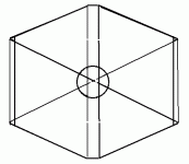
Flat like paraline, but eliminate the complex shape of parabolas.
Only suggesting a flattened triangular cone with flat reflections
at the edges where it folds back toward the center. Point source
from a single driver with narrow conical vertical coverage, and
wide horizontal dispersion. Same concept as Mantaray.
No parabolas intended to emulate a line source, which would be
too narrow vertical coverage for your app, and require stacking
many drivers (and parabolas) at greater expense to cover height
of all ears. Though not as many drivers as a standard line array.
If you can cut flat triangles, and afford one driver, there's nothing
more "plans" to it... And since the driver is behind a solid sheet of
wood, there are no worries of surviving a dart.
Danley also used a stack of offset paraolas to combine 8 drivers
into a single apparent point source with a 10degree vertical cone
(see Patricks 'square pegs' thread). Now THAT was complex design...
Attachments
Last edited:
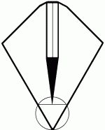
Twice the usual distance (including the internal fold) between front
and back of this baffle, you may not even need to close the back...
If space between dart machines is an issue, you can turn it sideways
and just build like one half of what I just drew. But then you probably
would want to close up the back of the speaker. Just another option...
and back of this baffle, you may not even need to close the back...
If space between dart machines is an issue, you can turn it sideways
and just build like one half of what I just drew. But then you probably
would want to close up the back of the speaker. Just another option...
Last edited:
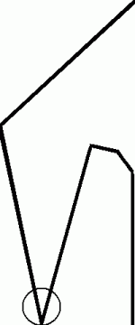
And speaking of offset, Even simpler:
Three layers of wood instead of five...
Only the middle layer any challenge.
Exit slot width = twice the thickness
of the middle layer of wood.
Again, half turned sideways (edge on)
would work fine too.
All straight edges, no parabolas...
If it looks curved, my bad drawing.
The top could go straight to a point,
it wouldn't hurt anything... I was
just obsessing on 'the vertical cone',
which was ridiculous since horns
prefer a flare at the end anyways...
The little extra bit at the top (if we
cut the reflectors simply straight)
would amount to such a flare...
Attachments
Last edited:
This high a Qts is why they may not need a sub in theory, but with tuning so far below Fs it will normally either need a sub or a high pass filter. Since a strong mid-bass is the goal, a max flat impedance TL is a much better choice, though it will still need ~2 ft^3/driver.
GM
Which idea is this in regards to?
I think 3-4 cu3 enclosure volume is do-able. Maybe even a bit more.
If you can cut flat triangles, and afford one driver, there's nothing
more "plans" to it...
I really need to research this a bit more so I can understand what you're talking about. 😀
At work today though. Not much gooogle time available.
I have at least 12" width and 48" height and 20" depth to work with.
What research? Its three flat layers of wood.
The back piece has a hole for the speaker.
The front piece has an exit slot cutout.
The middle piece (or pieces if you prefer)
is nothing more than a few strips of wood.
The back piece has a hole for the speaker.
The front piece has an exit slot cutout.
The middle piece (or pieces if you prefer)
is nothing more than a few strips of wood.
Last edited:
With those dimensional constraints, perhaps edge exit is best?
This looks even easier to build. Assuming the center layer will
not be solid where it isn't necessary, but simply made of strips...
I drew to 480x200 pixels, so should scale in good proportion.
You may want a few inches of baffle on either side of the slot
to hold the 180 degree horizontal pattern and to help keep it
from flopping over, since its so narrow. And might rattle if you
lean it against the dart machine for support. Maybe a cheap
piece of 2x4 lumber on either side of the front edge would do
the trick?
Attachments
Last edited:
What research? Its three flat layers of wood.
The back piece has a hole for the speaker.
The front piece has an exit slot cutout.
The middle piece (or pieces if you prefer)
is nothing more than a few strips of wood.
So the middle wood is what forms the "channels/path" of the horn?
Yeah, there are probably tons of calculations that go into designing the horn path/length/etc. I never did learn Hornresp or Akabak although it is on my to-do list for someday.
I can custom design sealed/vented/bandpass enclosures all day long.
But designing a horn is out of my comfort zone.
With those dimensional constraints, perhaps edge exit is best?
This looks even easier to build. Assuming the center layer will
not be solid where it isn't necessary, but simply made of strips...
I drew to 480x200 pixels, so should scale in good proportion.
You may want a few inches of baffle on either side of the slot
to hold the 180 degree horizontal pattern and to help keep it
from flopping over, since its so narrow. And might rattle if you
lean it against the dart machine for support. Maybe a cheap
piece of 2x4 lumber on either side of the front edge would do
the trick?
Is this a simple horn, kind of like Altec Lansing used to build way back in the day?
Or is there some kind of Paraline magic to it that I'm not seeing. 😀
Kenpeter,
I am having a hard time following your suggestions for Paraline and parabolas, or no parabolas for this bar room application. What exactly are you proposing? That CZ Eddie builds horns to get wide dispersion with cheap drivers? Almost any long horn stuck on the front of a driver will kill its HF response if not modeled correctly. Are those circles in your sketch supposed to represent the driver cone? A sketch with front and side views would be useful as I don't follow the current sketches at all.
Thanks
- Status
- Not open for further replies.
- Home
- Loudspeakers
- Full Range
- Ultra wide horizontal dispersion cabinet design?