I do remember the 12AU7 being recommended as a way to lower the gain on one of my tube amps. No other changes were needed in that instance.
That would definitely be the exception to the rule. I've often seen that advice given for guitar amps but trying to use a 12AX7 in a circuit designed for a 12AU7 (or vice versa) is almost always bad advice for a hifi amp. The electrical characteristics for the two tubes are drastically different and the same component values will yield vastly different operating points for the two tubes.
If you look at the plate resistors in common circuits using a typical 275 volt or so supply voltage, you'll see values around 22k for the 12AU7 and about 100k or more for the 12AX7. Quiescent plate currents with these ballpark values are around 5 mA for the 12AU7 and about 1 mA for the 12AX7. Again, this assumes a supply voltage in the 250-275 volt range; for very low plate supply voltages like used in the TubSuMo the differences might be smaller, but I'd need to simulate the circuit with the appropriate plate supply to know for sure.
Your statements made me look back at what was recommended back when I did that. I modded a Fender Blues Junior. The Blues Jr has two `12AX7 in the front of the preamp and a 12AX7 in the phase inverter position. The recommendation was to use the 12AU7 or 12AT7 in the phase inverter to lower the gain and reduce distortion. If memory serves me right, I ended up using 12AU7 because the 12AT7 caused oscillation. Might have just been a bad tube. This is cool. I'm learning something new, 😉
Hi Ray,
Voltage on emitter of Q2 is roughly 61V DC.
You are right, because of higher gain of 12AX7, I would recommend to increase degeneration resistors' values roughly 5 times, so that R32, R54 will be 220R, R31 pot - 50R.
Terry, for Low TIM Hybrid, you can try it as is - it is more heavily compensated, so excessive gain is going to slightly reduce distortion even further, still maintaining enough stability.
Cheers,
Valery
Thanks, Valery.
I ran a quick simulation as built but with no load on the tube input stage so I could isolate its behavior. With the 12AU7 the operating point looks fine, even at the low plate voltage: about 30 volts plate-to-cathode, about -1.1 volts grid-to-cathode, and about 1.2 mA plate current.
A sim with the 12AX7 didn't look as good. With the current source forcing about 2.5 mA for the pair of tubes and the low plate supply voltage, the 12AX7 is actually biased into the positive grid region. So I would probably stay with the 12AU7 in this particular circuit.
Thanks for your work making this design available to the DIY community.
Hi Ray,
6DJ8 is a slightly different creature. You are right, it is designed for cascodes (SRPP), so its sections are not the same. They are optimized for common-cathode (pins 6,7,8) and common-grid (pins 1,2,3) cascades, having different inter-electrode capacitances between the sections. It will work in both amps, mentioned above, but for TubSuMo lead compensation cap will need to be decreased ~50% (3.3pF instead of 6.8pF).
Cheers,
Valery
Hi Valery,
You're quite right about the tube sections not being identical in the original 6DJ8. But in the current production versions of the ECC88 from JJ and Electro-Harmonix (and others) the tube sections are the same, so they can be used in differential configurations and still take advantage of the tube's high transconductance and ability to perform well at relatively low plate voltages. I've used them successfully in a number of all-tube circuits. But I agree that the NOS 6DJ8 should probably not be used in this configuration.
Ray
Hi Valery,
Are you getting any closer to proofing the Tubsumo IPS? I have notice that the OPS boards have shipped. I do have a question about the OPS. When building the little mini OPS for the Slewmaster that uses these same outputs we discovered that either some additional capacitance needed to be added to N-channel outputs or the base stoppers needed to be different on that side to curb oscillation. Actually I ended up changing the base stoppers on those. You can read about it here.
Can you tell me why we don't need something like that here?
Thanks, Terry
Hi Terry,
Still waiting for transistors. They are processed by customs for two weeks already and I had to sign a paper, stating I will not use those transistors for terrorism or military purposes 😛
Transportation company estimates delivery next Wednesday... tough
Regarding the caps for N-channel - see schematic >HERE< - 220pF caps are there. PCB is updated accordingly - hope, the one you ordered is the right one 😉 Well, even if it's not - not a big deal, the caps are easily placed on the pins, although having them on PCB looks more elegant.
My tests showed exactly the same behavior, as in your case.
Cheers,
Valery
Hi Valery,
You're quite right about the tube sections not being identical in the original 6DJ8. But in the current production versions of the ECC88 from JJ and Electro-Harmonix (and others) the tube sections are the same, so they can be used in differential configurations and still take advantage of the tube's high transconductance and ability to perform well at relatively low plate voltages. I've used them successfully in a number of all-tube circuits. But I agree that the NOS 6DJ8 should probably not be used in this configuration.
Ray
Ray, many thanks for your inputs. I should have noticed positive bias for 12AX7 here. Well, it does not seem to lead to noticeable grid currents in this case, but still - good to know. 12AU7 is a better performer here, well - that's the one I designed the circuit for 🙂
Info on 6DJ8 with identical sections is also useful - a good tube, worth trying.
Cheers,
Valery
I'm happy to be able to contribute in some small way. FYI, the 6CG7 is also a tube worthy of consideration in the IPS. It's similar in characteristics to the 12AU7 but is considered more linear by the tube fanatics. It is also in current production at reasonable cost.
Updated BOMs
Hi All,
Based on request from Harry (very valid one 😉), I have updated both BOMs with capacitors' lead spacing values.
Also note, I have reduced the values of C6, C7, C21, C22 from 100uF to 22uF (did it some time ago, just forgot to reflect on schematic). Having two cap multipliers (one on IPS board, the other one on OPS one), there's more than enough capacitance there.
As I mentioned earlier, transistors are expected mid-next-week.
Looking forward...
Cheers,
Valery
Attachments
Hugh, you're absolutely right, as usual 🙂
I'll try. If the weather is dry, I will definitely do some scate-boarding
Unfortunately, jumping from airplanes is a sort of an addiction, though I do it much less these days, than I did 3-5 years ago (up to 400 jumps per year 😱)
I'll try. If the weather is dry, I will definitely do some scate-boarding
Unfortunately, jumping from airplanes is a sort of an addiction, though I do it much less these days, than I did 3-5 years ago (up to 400 jumps per year 😱)

IPS first power-on
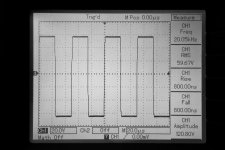
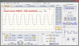
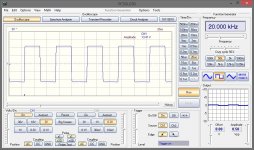
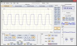
The firs impression is pretty cool. Great performance at wide range of signal parameters. Attached is a square wave response at 20KHz and 120V amplitude 😱
Next will be some DC servo tune-up, testing noise levels for blue and double-red LED options for VAS cascode offset and distortion level measurements.
After that - overall testing together with OPS.
Out for scateboarding for 2-3 hours (Hugh, as promised 😉).
Cheers,
Valery
Attachments

IPS standalone
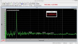
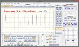
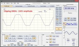
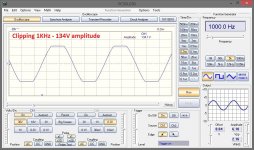
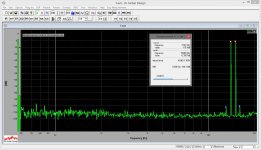
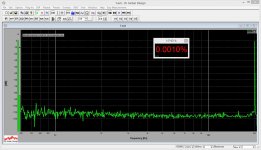
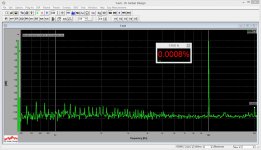
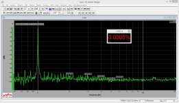
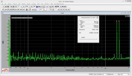
OK, some measurements on IPS alone (~20Kohm resistive load).
I deliberately ran the square waves at high swing - that's where some artifacts normally appear.
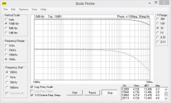
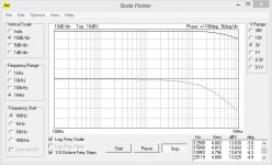
Good points - only 3.6 degrees phase shift @ 20KHz, nice clipping, very good square wave response, THD / IMD - no comments.
Pretty fast VFA. Well, OPS will slow it down - we'll see, to what extent...
Checked with a pair of blue LEDs in VAS offset circuit as well as with the double-red pairs. No difference in noise floor. Just not at all. Nothing. Left double-reds for now, but either can be used.
So far so good... Next test - with OPS attached.
Cheers,
Valery
OK, some measurements on IPS alone (~20Kohm resistive load).
I deliberately ran the square waves at high swing - that's where some artifacts normally appear.
Good points - only 3.6 degrees phase shift @ 20KHz, nice clipping, very good square wave response, THD / IMD - no comments.
Pretty fast VFA. Well, OPS will slow it down - we'll see, to what extent...
Checked with a pair of blue LEDs in VAS offset circuit as well as with the double-red pairs. No difference in noise floor. Just not at all. Nothing. Left double-reds for now, but either can be used.
So far so good... Next test - with OPS attached.
Cheers,
Valery
Attachments
-
 01-zIMD-14-15KHz-4VRMS.JPG301.8 KB · Views: 213
 -
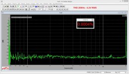 01-THD-20KHz-4VRMS.JPG290.5 KB · Views: 222
 -
 01-THD-10KHz-4VRMS.JPG293.3 KB · Views: 258
 -
 01-THD-01KHz-4VRMS.JPG295.2 KB · Views: 259
 -
 01-SQR-100KHz-120V.JPG213.8 KB · Views: 227
 -
 01-SQR-020KHz-120V.JPG208.3 KB · Views: 220
 -
 01-SQR-001KHz-120V.JPG211.2 KB · Views: 224
 -
 01-SIN-CLIP-20KHz-120V.JPG205 KB · Views: 969
 -
 01-SIN-CLIP-01KHz-120V.JPG205.3 KB · Views: 1,001
 -
 01-BODE-120V.JPG101.9 KB · Views: 1,036
Looking good! Can't wait to see how it goes attached to the OPS. Will you test it with both OPS, the new lateral one and the slewmaster?
Thanks, Terry
Thanks, Terry
Done! 🙂
Alright, here we go.
Measurements are done with 8R load.
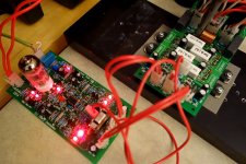
This one is with the Lateral FETs OPS.
One poorly soldered wire gave me some really hard time. Everything looked fine during measurements, but when I disconnected the measurement system for doing some listening, it started giving some 0.7V negative offset at the output. Then it slowly increased and at about 1V protection triggered. Drove me insane 🙂 Almost an hour of tough troubleshooting, until I realized - a thick wire, connecting G1 and G2 grounds is soldered, but does not really contact the trace at G2. During the measurements, the ground was coming to IPS module through the cables. It was a long way, but it was a connection. As soon as the measurement system was disconnected, IPS's ground started floating...
I will probably re-measure this setup as it may show even better results with the proper ground wire. Can't do it now - exhausted 🙂
Well, after proper soldering, it plays nicely. Dynamic, detailed, natural sound. Very pleasant. Will ride it tomorrow at high volumes.
Both setups are rock stable (76 degrees of phase margin according to simulation). No sign of oscillation.
Terry, you can order the PCBs now 😉
Test with SlewMaster-based IRFP OPS - see the next post.
Alright, here we go.
Measurements are done with 8R load.
This one is with the Lateral FETs OPS.
One poorly soldered wire gave me some really hard time. Everything looked fine during measurements, but when I disconnected the measurement system for doing some listening, it started giving some 0.7V negative offset at the output. Then it slowly increased and at about 1V protection triggered. Drove me insane 🙂 Almost an hour of tough troubleshooting, until I realized - a thick wire, connecting G1 and G2 grounds is soldered, but does not really contact the trace at G2. During the measurements, the ground was coming to IPS module through the cables. It was a long way, but it was a connection. As soon as the measurement system was disconnected, IPS's ground started floating...
I will probably re-measure this setup as it may show even better results with the proper ground wire. Can't do it now - exhausted 🙂
Well, after proper soldering, it plays nicely. Dynamic, detailed, natural sound. Very pleasant. Will ride it tomorrow at high volumes.
Both setups are rock stable (76 degrees of phase margin according to simulation). No sign of oscillation.
Terry, you can order the PCBs now 😉
Test with SlewMaster-based IRFP OPS - see the next post.
Attachments
-
 DSC03439.JPG331.8 KB · Views: 1,640
 -
 11-zIMD-14-15KHz-4VRMS.JPG197.2 KB · Views: 234
 -
 11-THD-20KHz-4VRMS.JPG192.7 KB · Views: 214
 -
 11-THD-10KHz-4VRMS.JPG192.8 KB · Views: 223
 -
 11-THD-01KHz-4VRMS.JPG194 KB · Views: 239
 -
 11-SQR-100KHz-13V.JPG141.4 KB · Views: 219
 -
 11-SQR-020KHz-13V.JPG139.8 KB · Views: 221
 -
 11-SQR-001KHz-13V.JPG142 KB · Views: 202
 -
 11-BODE-13V.JPG69.8 KB · Views: 248
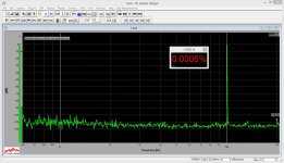
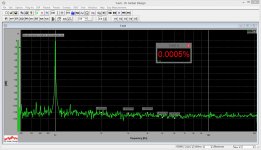
Measurements with EF drivers + IRFPs at the output.
Pretty close to the previous one.
Slightly higher distortion at 10KHz, but very slightly lower at 20 KHz.
Anyway, overall distortion level is so low - it doesn't really matter...
Need to listen an high volumes to see if there are some audible nuances.
Also - would be cool to test with BJT OPS, just don't have one in hand now.
Ah, corrected a couple of R values in IPS - will drop an updated schematic/BOM tomorrow. No PCB changes nevertheless.
Need to have some sleep. Troubleshooting the loose wire "killed" me 😀
Cheers,
Valery
Attachments
-
 21-THD-20KHz-4VRMS.JPG195.6 KB · Views: 155
 -
 21-THD-10KHz-4VRMS.JPG196 KB · Views: 167
 -
 21-THD-01KHz-4VRMS.JPG196.3 KB · Views: 179
 -
 21-SQR-100KHz-13V.JPG140.3 KB · Views: 163
 -
 21-SQR-020KHz-13V.JPG139.4 KB · Views: 158
 -
 21-SQR-001KHz-13V.JPG139.3 KB · Views: 174
 -
 21-BODE-13V.JPG69.6 KB · Views: 478
 -
 21-zIMD-14-15KHz-4VRMS.JPG200.3 KB · Views: 155
- Home
- Amplifiers
- Solid State
- Ultra-high performance, yet rather simple - hybrid and more!