That is freakin' funny .... 😀
Are you saying my trafo is a fat slob ?
I better girdle it with a "flux band" , just in case.
Edit - "belly band" proper (google) - for pregnant trafo's (below).
OS
Are you saying my trafo is a fat slob ?
I better girdle it with a "flux band" , just in case.
Edit - "belly band" proper (google) - for pregnant trafo's (below).
OS
Attachments

Last edited:
describe "core band" and "flux band" for us.
The internal inter-winding screen, does it have a correct engineering name?
The external winding around an EI or a toroid, does it have a correct engineering name?
The internal inter-winding screen, does it have a correct engineering name?
The external winding around an EI or a toroid, does it have a correct engineering name?
Dare we ask "are you pregnant, how many weeks?"That is freakin' funny .... 😀
Are you saying my trafo is a fat slob ?
I better girdle it with a "flux band" , just in case.
Edit - "belly band" proper (google) - for pregnant trafo's (below).
OS
or "are you just fat"
Slap !
Hi Guys
Yes, a bottom washer helps confine the EMI field.
Many companies use aluminium chassis for its nonmagnetic properties, so there is electrostatic shielding but not magnetinc shielding. The same applies to the grades of stainless steel that are actually "stainless" and thus nonmagnetic.
CORE BAND and FLUX BAND are accurate terms that describe what the piece does and make sense. Electronics uses precise terms so people can understand what is being discussed. Belly-band sounds like something for an obese and disgusting slob with a genetic issue or poor will power. - certainly clinging to ignorance Why not thorax band, or head band, or around-the-outside band...
Have fun
You are far too conservative. 'Belly Band' happens to be transformer winders vernacular for the terms you illucidated on above. So what? Let's not become STEM snobs. Engineers can use slang and still do serious technical work.
Jn maybe you can answer another question from me. If I place the aluminum or ferrous cover on one of my amps (in development) there is 6-10 dB drop in hum. The cover is not touching any part of the transformer (a torroid). I have assumed that what is happening here is the stray electric field from the transformer is being captured by the cover with the whole case forming a loop around the transformer. So rather than intersecting any cabling or local circuits, it flows in the amplifier casing. It has a belly and and a screen.
Boht alum and ferrous will have eddy currents. The net effect of the eddies is to try to constrict the overall magnetic field lines. At 50/60, aluminum is not as effective as ferrous, in that the mag field lines will also follow the permeability of the ferrous.
Mu metal has very low field tolerance, it can saturate very easily, and when it saturates, much of the additional flux will just pass through.
If it's e field, aluminum foil will do the job. If it's not e-field the foil will produce no effect. Try it to verify if it's E or M.
jn
Hi Guys
The electrostatic screen between the primaries and secondaries is called exactly that.
With EI PTs there is a tonne of magnetic leakage and far less with a toroid but still some because toroids are made in an economical way. Excluding ferrite cores, mains-operated toroids use a strip of core material wound spirally onto itself to make a core of the desired size. There is an obvious discontinuance of material since it is made this way, so some tiny leakage based solely on the core construction.
The copper windings could contain the above toroid's leakage if they covered the core 100%. As explained previously, the windings do not provide full coverage and then there is a major coverage discontinuity at the lead breakout. AndrewT suggests that sometimes a second electrostatic screen might be placed as the outside layer - don't know if that it true or not - but if this were so, it might help contain some of the leakage.
Special winding techniques are used to reduce noise output of the transformer but these cost a lot in time.
One of the easiest things we can do to help reduce EMI from the PT is to use a device that is quite overrated for the maximum load expected. Leakage seems to rise nonlinearly as the PT approaches its capacity, as does temperature rise. if you spec a PT for a lower temp-rise then its EMI will be lower as well, generally. The downside of a larger PT is more weight, more space required and higher cost.
Another thing to do with toroids is to always use full-wave rectification - never half-wave. Discontinuous conduction and loading creates a tonne of noise that feeds back to the mains and to other windings. These effects can be reduced using RCs even for full-wave.
Large PTs (300VA+) should have DC blockers on the mains. below this VA the winding resistance is usually high enough to negate the effects of mains asymmetries caused by noise.
I've tried thicker chassis material and different materials to try to contain PT EMI. The things that worked were using steel cup washers even if the PT center was potted, using cup washers above and below, specifying core bands, specifying electrostatic screens, and using mu-metal. It was actually a friend who went for the mu-metal and he found that having it cut to shape allowed him to connect the pieces using small brackets. There was no advantage trying to solder or weld the edges or seems in the covering due to the frequencies involved. The mu-metal worked in his app, which is a tube mic pre.
OStripper, your PT may be obese if it is in the kVA range... where does transformer obesity begin? 225VA? 300VA? 626VA?... and it must begin right at birth before it even gets to you...
Have fun
I've tried thicker chassis material and different materials to try to contain PT EMI. The things that worked were using steel cup washers even if the PT center was potted, using cup washers above and below, specifying core bands, specifying electrostatic screens, and using mu-metal. It was actually a friend who went for the mu-metal and he found that having it cut to shape allowed him to connect the pieces using small brackets. There was no advantage trying to solder or weld the edges or seems in the covering due to the frequencies involved. The mu-metal worked in his app, which is a tube mic pre.
Yes , the cups work.
I use a round Si/Fe disk below (under my bottom thick neoprene washer)
and the supplied cup above.
Very little radiated hum (with my amplified coil) above and below. On
the sides of my "obese" 😀 toroid , only at that breakout point is any
considerable field.
The best would be a full "can" , like in the Parasound's . Can't find one
for my "fattie". Antek makes <400VA sizes - that's it.
The monster Genesis Stealth had 2 - 800VA's floating in epoxy contained
in a 1/8" steel box. Thing weighed 20kG+ !!
OS
Hi Guys
The metal potting cans tend to be more cosmetic than functional for shielding. My toroid maker adds core material inside the can - called a "cup" whether plastic or metal in the industry - and has done mu-metal versions for my friend. The metal can is no substitutue for a core band - you still should specify that if you want the looks of a potted PT.
Potting is done one of two ways generally. Intuitively the whole space around the PT is filled with epoxy as two pours, one before and one after the transformer is set in place. The variation of this is to use sand for most of the fuller. Although drilled holes or inserts work okay for smaller VAs, a through-hole for a large bolt is the surest way to secure the thing. years ago I had some PTs made and used a stainless U bolt for the mount, embedded in the epoxy so the two threaded ends stuck out as studs.
A potted PT easily weighs up to twice what a nonpotted PT does.
I may be a bit more "anti-belly" than I should be, but recently lost 12kg - it feels like 25 pounds... haha (anti-belly not equal to antebellum)
Have fun
describe "core band" and "flux band" for us.
The internal inter-winding screen, does it have a correct engineering name?
The external winding around an EI or a toroid, does it have a correct engineering name?
Andrew I believe the term is Goss band. At least that's what Terry at cantebury windings calls them
I don't remember saying that.AndrewT suggests that sometimes a second electrostatic screen might be placed as the outside layer - don't know if that it true or not - but if this were so, it might help contain some of the leakage.
I can't see why that would apply.
That makes me wonder what I did say and whether my wording gave some ambiguous meaning that I had not intended.
Any chance you remember where I posted that?
Report: 0 (okay... 0.001 maybe 🙂) hum now...!
Pillars (in my case):
I hope activating the other side will not ruin the silence.
Thanks for everybody..!
Pillars (in my case):
- lowering FB values (low impedance FB)
- core band
I hope activating the other side will not ruin the silence.
Thanks for everybody..!
Tip, for all your signal cables.Report: 0 (okay... 0.001 maybe 🙂) hum now...!
Pillars (in my case):
Trafo washer not tested yet but I'll as soon I get one (or two... 😉).
- lowering FB values (low impedance FB)
- core band
I hope activating the other side will not ruin the silence.
Don't use expensive audiophile ones. Use CAT6 network ones.
Use two twisted pairs, hot and ground, for the two channels both connected to the source and target hot points and ground.
Rely the shield to the source ground, not to the target one.
You can try to use the two free pairs to connect the chassis earth together, or the grounds, or just let them connected (Like the shield) to the source.
Thanks for the tip Esperado!
Please help..! 🙂
(I just rearranged the earth wires in my whole system.
Now every device (func.gen., PC, scope, amp) uses the main AC earth point in the
right way and when they all are connected no ground loop and hum is created...)
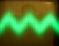
But I noticed at the output there is a ~450kHz wave around 15mVpp as attached.
First I thought cool, its another oscillation... but its there even after turning off the amp (and discharge the PS).
Then I looked around a bit and saw that it's already there @ the signal (RCA) GND...
The scope's
If I increased the 10nF to 220nF the wave were eliminated at the RCA GND but at the amp output it is still there.
It is just a measurement error? The scope's GND isnt at the right position?
Then I tried to plug the scope to an un-earthed outlet but the result was the same.
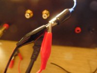
And then I reduced the problem to the root (without any amp parts involved!) I guess:
I have the same and exact result when I just short my scopes wires and then I connect it to the earth of my amp as attached...
Why this is happening and how should I eliminate it. Its very frustrating to chase an oscillation when its not even a real one... 😀
Please help..! 🙂
(I just rearranged the earth wires in my whole system.
Now every device (func.gen., PC, scope, amp) uses the main AC earth point in the
right way and when they all are connected no ground loop and hum is created...)
But I noticed at the output there is a ~450kHz wave around 15mVpp as attached.
First I thought cool, its another oscillation... but its there even after turning off the amp (and discharge the PS).
Then I looked around a bit and saw that it's already there @ the signal (RCA) GND...
The scope's
- GND: is earthed so I put it on the earth point in my amp which is separate via a 10R||10nF as adviced earlyer.
- "hot wire" is at RCA GND
If I increased the 10nF to 220nF the wave were eliminated at the RCA GND but at the amp output it is still there.
It is just a measurement error? The scope's GND isnt at the right position?
Then I tried to plug the scope to an un-earthed outlet but the result was the same.
And then I reduced the problem to the root (without any amp parts involved!) I guess:
I have the same and exact result when I just short my scopes wires and then I connect it to the earth of my amp as attached...
Why this is happening and how should I eliminate it. Its very frustrating to chase an oscillation when its not even a real one... 😀
Attachments
Fluorescent lights (tubes and compact), solder station, SMPS LED lights, SMPS anything.
All these send out interference and the bad ones send out a lot.
Go around the room and switch off everything. Maybe do the adjacent rooms as well.
All these send out interference and the bad ones send out a lot.
Go around the room and switch off everything. Maybe do the adjacent rooms as well.
I posted this one for the first time to my other thread (stability) but then I moved rather here, OS's reply there was:
You are picking up the "filth" of the 21st century.
Most likely your PC. Harmonics of cheap chinese CFL , other
cheap SMPS's can cause this RF hash , as well.
For your audio , filter across the ground loop breaker and/or
an AC input filter.
OS
New experiment: if I plug my scope and my amp to an unearthed outlet then the wave is gone...
If either of them is earthed then its appearing immediately...
If either of them is earthed then its appearing immediately...
Pff, yeah, it was indeed my PC... It was a bit tricky though... First I turned into sleep. Nothing....
Then I switched it of. Nothing... Then I plugged it off. Yesss...
Already when its plugged in it produces this garbage.
Now I have to use my amp and the scope "unearthed"... :-/
Is there another, more elegant way to solve this while my PC is plugged..?
(With all devices earthed as they should be of course...)
Methinks you have a classic ground loop there (via safety earth and ground connections in the setup). Either this is acting as an aerial, or safety earth potential is differing between the two outlets. The latter can happen if return current from the PC travels along the cable between the outlets, and then capacitively couples onto the safety earth conductor. Jensen Transformers' Bill Whitlock has studied this in some detail. Or maybe it is the power supply's mains filter which dumps this stuff onto protective earth.
Possibly your mains wiring daisy-chains a number of outlets (bus topology). Star topology would help here. Unfortunately renewing the electrical installation tends to be a major mess and expensive to boot.
Hi-Fi manufacturers tend to minimize mains coupling as far as possible, using transformers with shield windings for reduced capacitive coupling if need be. And they usually don't safety earth their stuff but go for double insulated instead. All for good reason. Unfortunately this only works for linear supplies, not so much for SMPS.
PS: How'd you people know I had a bit of a "power supply day" today? Opened up Sony AC-240 (found simple unregulated supply with little ceramic caps across rectifier), tried out TP-Link Wifi router on oldschool 1200 mA linear regulated brick (definitely a fair bit less hash on MW compared to stock "Leader" brand 12V/1.5A SMPS). Said brick needs about 4 W in idle just for itself though, so I kept looking, and lo and behold, our old DSL router had a chunky linear wall wart with 12V / 1200 mA and correct plug and polarity - perfect. Not bad for something that was just floating around in the way for months. I am guessing power consumption still is a bit higher than before, but what doesn't one do for a more "DX-friendly" home. It occurred to me that an efficient (as far as possible) linear universal power supply could be a real niche, thankfully I didn't need to solve that problem right now.
Pff, yeah, it was indeed my PC... It was a bit tricky though... First I turned into sleep. Nothing....
Then I switched it of. Nothing... Then I plugged it off. Yesss...
Already when its plugged in it produces this garbage.
Now I have to use my amp and the scope "unearthed"... :-/
Is there another, more elegant way to solve this while my PC is plugged..?
(With all devices earthed as they should be of course...)
I have had these troubles. The PC is an offender from both the motherboard -
The 1.5V huge CPU SMPS , the main SMPS , local oscillators on PCI
and PCI-E cards all contribute.
Best way is to optically couple your audio/PC. (DAC/Toslink)
Then you can actually
run audio stuff and the PC off different house circuits (grounds).
Physically separate your PC (with distance). "Anally" filter your audio
against the dirty SMPS pulses that manifest on a modern power line.
Power conditioners will work ( common-mode + RF filter combo).
OS
- Status
- Not open for further replies.
- Home
- Amplifiers
- Solid State
- Ultimate Hum Terminator Thread