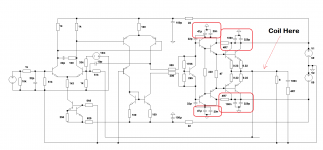
The coil is in the right place after the FB/zobel point, before the speaker out with a paralell, magnetic, wirewound 5W 10R resistor.
BTW: based on Esperado's VFA/CFA article already my amp is "half CFA" now 🙂 so the FB Zs are low! (2k3 / 47R)
Maybe the foil shields something other on that part..?
But it was so obvious when I searched for the right position that around the coil it brought dead silent...
BTW: based on Esperado's VFA/CFA article already my amp is "half CFA" now 🙂 so the FB Zs are low! (2k3 / 47R)
Maybe the foil shields something other on that part..?
But it was so obvious when I searched for the right position that around the coil it brought dead silent...
The coil is in the right place after the FB/zobel point, before the speaker out with a paralell, magnetic, wirewound 5W 10R resistor.
BTW: based on Esperado's VFA/CFA article already my amp is "half CFA" now 🙂 so the FB Zs are low! (2k3 / 47R)
Maybe the foil shields something other on that part..?
But it was so obvious when I searched for the right position that around the coil it brought dead silent...
What kind of foil is it?
Something Si based, my trafo maker sent me it, thats what they use for belly band.
If I am right that's what the core is made from as well.
If I am right that's what the core is made from as well.
Yeah it's very usefull probe material indeed..! 🙂
BTW: I tried some other magnetic metals and they worked as well but this foil is easy to tear, bend and "thicken".
BTW: I tried some other magnetic metals and they worked as well but this foil is easy to tear, bend and "thicken".
You say it just can not happen ??
The fact that cortez "foiled" it , throws a wrench into that conclusion.
It was the redirection of my "breakout point" that eliminated my last
10db of hum.
This effect was much more noticeable on a VFA , BTW.
OS
OS there is some other mechanism causing this.
Model it I n LTspice to see if you can explain it.
I doubt that a c. 3-5 uH L can drive hum in a speaker.
OS there is some other mechanism causing this.
Model it I n LTspice to see if you can explain it.
I doubt that a c. 3-5 uH L can drive hum in a speaker.
Won't it feed back into the feedback circuit and get amplified? The feedback circuit connects right at the inlet to the inductor.
and gets divided down by the NFB ratio.Won't it feed back into the feedback circuit and get amplified? The feedback circuit connects right at the inlet to the inductor.
It is RF that bypasses the upper NFB resistor by taking the easier route through the cap (sometimes used across it) that gets amplified. Not the LF.
No, the 51k in combination with it's 1k partner attenuates the LF interference that gets in via the speaker cables.
There is no 10pF across the 51k NFB upper leg in this schematic.
Remember, every cable connection to an amplifier is an INPUT, even the output cables and the supply cables and the ground cable.
Adding RF attenuation to every cable entry through the Chassis and taking that attenuating filter direct to Chassis helps remove external interference effects from the amplifier.
Adding some RF attenuation as the cables reach the PCB helps with reducing the effects of internally generated interference. But I tend to only add this to the +-Supply cables, to the +IN input cable and to the speaker output cable.
Yes the output Zobel and the local decoupling act as RF attenuating filters against internally generated interference.
Last edited:
The 100n+4.7R zobel needs to be right at the output of the power transistors, and connected directly to local ground. Putting it on the wrong side of the inductor may be one of your problems, if that schematic is accurate.
If your amp has a noise floor at -115db and your "hum" is at -105db, that's 5.6uV of hum. So if you're using a soundcard or LNA to measure "hum" then it seems believable for the coil to pick it up. I doubt it would be audible though.
If your amp has a noise floor at -115db and your "hum" is at -105db, that's 5.6uV of hum. So if you're using a soundcard or LNA to measure "hum" then it seems believable for the coil to pick it up. I doubt it would be audible though.
No, the 51k in combination with it's 1k partner attenuates the LF interference that gets in via the speaker cables.
There is no 10pF across the 51k NFB upper leg in this schematic.
Remember, every cable connection to an amplifier is an INPUT, even the output cables and the supply cables and the ground cable.
Adding RF attenuation to every cable entry through the Chassis and taking that attenuating filter direct to Chassis helps remove external interference effects from the amplifier.
Adding some RF attenuation as the cables reach the PCB helps with reducing the effects of internally generated interference. But I tend to only add this to the +-Supply cables, to the +IN input cable and to the speaker output cable.
Yes the output Zobel and the local decoupling act as RF attenuating filters against internally generated interference.
Thanks Andrew. I think I know what capacitor you meant. it's not used here.
The 100n+4.7R zobel needs to be right at the output of the power transistors, and connected directly to local ground. Putting it on the wrong side of the inductor may be one of your problems, if that schematic is accurate.
If your amp has a noise floor at -115db and your "hum" is at -105db, that's 5.6uV of hum. So if you're using a soundcard or LNA to measure "hum" then it seems believable for the coil to pick it up. I doubt it would be audible though.
Don't go by the schematic I posted. It was just a hypothetical question.
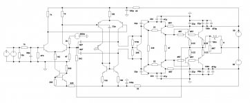
Oh !This is my latest (coil after the zobel of course... 🙂).
HF: 2 x 4p7 from VAS + 1 x 33pF @ current mirror.
FB: low Z! (2k3 + 47R now)
I dont know why the coil caused the hum but I can measure/try whatever you are curious to...!
The coil L have to be in parallelel to the 8 ohms. Do you really want to set a serial 8 Ohms at all the frequencies in serial with your speakers ?
That's a lot of gain. Most of us manage with 20times to 30times. You have 2k3 (not an E24 value) divided by 47r plus 1 = ~50times (+34dB).This is my latest ...................
FB: low Z! (2k3 + 47R now)
I dont know why the coil caused the hum but I can measure/try whatever you are curious to...!
What is the peak voltage across the 2k347 combination?
What is the peak instantaneous dissipation?
What is the distortion due to tempco?
Sorry, I dont want to off @ the HUM thread so I replied in the other thread:
http://www.diyaudio.com/forums/solid-state/270230-heatsink-vs-os-stability-3.html#post4288458
http://www.diyaudio.com/forums/solid-state/270230-heatsink-vs-os-stability-3.html#post4288458
- Status
- Not open for further replies.
- Home
- Amplifiers
- Solid State
- Ultimate Hum Terminator Thread