Tranny's
Hi all I was quoted a lead time of 4 weeks.........so I guess we are now down to approx 3 weeks!
🙂 🙂 🙂
Hi all I was quoted a lead time of 4 weeks.........so I guess we are now down to approx 3 weeks!
🙂 🙂 🙂
Just waiting for the heatsinks to turn up now (hopefuly they will be here thismorning), so I will probably be packing them up on wednesday afternoon after my exam to send out on thursday.
Rectifiers........landed
Wow thanks Bigparsnip...........got the recitifiers....they look the business.....can't wait to use them!!!!! Many many thanks......
........Kind Regards
Richard (D3)
Wow thanks Bigparsnip...........got the recitifiers....they look the business.....can't wait to use them!!!!! Many many thanks......
........Kind Regards
Richard (D3)
FET Choice
Have received a quote from the contact earlier in the thread for FETs, however they cannot supply 044's only 240's. I think these should work with 16V,but seem to remember that they are better run at 25V or higher, despite searching I cannot find any reference on DIyaudio.
What are other people using at what voltage?
I wiil be placing an order for NTC thermistors from Buerklin as mentioned before if anyone is interested.
Also looking to order Vishays and Blackgates etc to populate the board if anyone interested.
Simon
Fets & components
I believe that you can use 044's up to arround 20v........with the trannys we are using.......we will have a rectified voltage of around 24v - 25v !!! I am considering using a CRC setup to lower voltage a touch ............ somewhere in the region of 21v or so.......
so I am tempted to still go with 044........as they like biasing........
I don't really need huge wattage.....I want more drivability into 4 ohms.
With regard to capacitors and resistors + thermistors.........Yep I am definatley in on that.............it makes sense to try and standardise if poss afterall we all have the same trafo's...........
Kind Regards
Richard
I might be intrested in tyring to get my hands on some of the passive components too (although, I may need diferent values, as I will probably be runnig at a much lower power level than you lot), especialy some decent resistors.
!!!!TRANNY UPDATE!!!!
Just a quick post.....the Trannys are due to ship the middle of next week.......
D3😀 😀 😉 😉 😀 😀
Just a quick post.....the Trannys are due to ship the middle of next week.......
D3😀 😀
😉 😉 😀 😀 Tranny update!
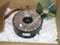
Air link have confirmed that they have wound the transformer
as two lots of 500va …. As they can’t wind the gauge req for 1000va
…….18v x2-0-18v x2
Wiring Colours:-
Orange white 18v
Yellow black blue Green Neutral
Red Pink 18v
tj contact me I need your full name
Magura contact airlink they have a problem with bfpo address
Re: Tranny update!
Sounds like a BS excuse to me...they are offering 5000VA tafos on their website....now 5000VA is heavy gauge wire????
Magura🙂
D3 said:Air link have confirmed that they have wound the transformer
as two lots of 500va …. As they can’t wind the gauge req for 1000va
…….18v x2-0-18v x2
Sounds like a BS excuse to me...they are offering 5000VA tafos on their website....now 5000VA is heavy gauge wire????
Magura🙂
Hi, I have finished my parts list to go shopping for almost all of the rest of the parts I will need to build my X now (well, at least the bits that go on the PCB), and I was wondering if anyone else was interested in getting them at the same time, as hopefully some of the parts shoud drop in price that way. I have attached a spreadsheet of all of the parts I will be ordering and where from, prices (not including VAT) etc, so as most of the parts son't vary from one design to another, i should be quite easy to accomodate all of the possible different designs out there quite easily.
Let me know if you do want to group up on this, as I will probably be putting the order in some time in the next two weeks now.
Andrew.
Let me know if you do want to group up on this, as I will probably be putting the order in some time in the next two weeks now.
Andrew.
Attachments
Parts
Count me in!!!!
How about buying quite a few 1N5239B so we can have very well matched sets.............critical on this project.............
I would be in for 3X parts list................however I have not checked out values etc for the ps............I will be needing....
When are you ordering.............next month would suit me!
xformers arrived today - going to hosptial tonight along with delivery man and fiances' mum (who all had the pleasure of lifting the ******s!) Just to clarify - we have to wire the two +18V secondaries in parallel and the same for the -18V to get 1000VA?
Finally, I have a general query. I (as I'm sure are others) am planning on fixing the circuit board to the rear panel. This means short signal path. I am also planning on mounting the xformer at the front, mounted vertically. My problem is that I have to route the mains cable from one end of the chassis to the other, more importantly, passing the amp board in close proximity. I have thought about routing it inside a hollow section of square aluminium tubing - but wasn't sure if it'd make much difference?
How far away should the internal mains cable be? And what tricks are there to reduce inducing a 50Hz ring into the amp?!
Thanks,
Gaz
The easy solution would be to run the mains in a copper plumbing pipe. A copper pipe would make a great shield.
Magura🙂
Magura🙂
Parts....
Hi Andrew,
I would like to join in the parts group buy with 2 x partslist.
Anything I can do to help? I've got a load of mail-lite envelopes and anti-static bags I can send you if you want?
Cheers
Jon 🙂
Hi Andrew,
I would like to join in the parts group buy with 2 x partslist.
Anything I can do to help? I've got a load of mail-lite envelopes and anti-static bags I can send you if you want?
Cheers
Jon 🙂
PSU and Parts
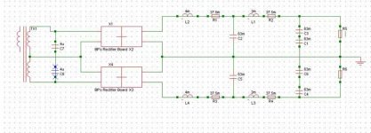
Planning on this, comments please.
Inductors from Jason source. R1 to R4 would be NTC Thermistors, ( also on primary side not shown. )
As mentioned before looking to buy these soon either Epcos' BS57237S0100M000 though not 4.2 but 3.7A as per data sheet so probably to low a current value.
Actual CL60 replacement is Epcos' BS57238S0509L002 6.4A. Quoted 1.40 each for these.(qty>50) Let me know if interested.
On the other parts would prefer Black Gates for all caps where possible. BP have you checked out www.thlaudio.com for a quote.
Attachments
SineEra Power Supply
Please shoot me down if i've got this wrong - i'm no expert and there are plenty around the forum that are, but i have taken a look and think you should not use C1/C3 in series - you are doubling the voltage handling of the capcitors but halving the capacitance - i would suggest moving C1 to the left of L2 to create a CLCLC pi filter, obviously ditto the lower half of the circuit.
I don't know what C7 & C8 are doing (but as i said, i'm no expert) they are inevitably in parallel with some (but not all) of the diodes on BP's rectifier board and may have an adverse affect (BP to comment please?).
Why are you using thermistors and inductors? If you need more resistance to drop your supply rail voltage then just increase the coil size of the inductors (the DCR of the coil will increase proportionately). I've just never seen the two used together before....
C7 and C8 are not quite duplicating the capacitors on the rectifier PCB, as the snubbers are in series with the reseitors to give a more controled damping response. However, I doub't that you will need these in your supply and they may easily ommited. As far as using the thermisotors and inductors in series, there are two things I could say:
firstly, if you are using the thermistors to simply act as a type of soft start circuit for the supply then I would leave them in, as they will ease the turn on current rush significantly.
however, if you are placing them there to act as a resistance in the fully opperational power supply, I would say to take them out an either use a bigger inductor (with higher Rdc) to get the desired output voltage, or to simply use fixed resistors as these would be a lot cheeper (although, in a choke smothed supply, they may not be entirely neccessary)
Anyway, hope that was helpful in some way (and that there aren't too many spelling mistakes, as I just got back from the pub) and I look forward to finding out what you were intending them do do in your supply.
- Status
- Not open for further replies.
- Home
- Amplifiers
- Pass Labs
- UK Aleph-X PCB orders