Delivery confirmation
BuzzLiteYr here; package was picked-up yesterday, delivery on 14 Aug.
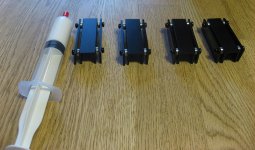
All expected components arrived in good condition. Boards look Mahvelous!
Thank you!
BuzzLiteYr here; package was picked-up yesterday, delivery on 14 Aug.
All expected components arrived in good condition. Boards look Mahvelous!
Thank you!
Other than the docs offered on the HomeCinema site, and the excellent SMD soldering approach, is there any other build guide available offering more detail for those of us unfamiliar with this project? I've perused this thread from the beginning, and tried to find what bits and pieces I could from posts. Anyone in the past 5 years done a 'Hitchhikers Guide' to the MUSE USG Pre project.... walk-through of building, testing, adjusting, etc. Assembly tips and techniques? Pitfalls to avoid, that sort of thing. 🙂
Hi, I have what I believe to be few pieces of 2BL389 and 2SJ109 that I bought 8 or so years ago. Is there a recommended / straight forward method of testing them before I get too far into the MUSE build? I have a scope, decent multimeter (fluke 289), and a few cheaper multimeters and would appreciate being pointed in the right direction.
Hello, there are few interesting things to read, on my side I recommend what was written by Erno Borbely or Nelson Pass.
JFETs: The New Frontier, Part 1 | audioXpress
By the way when selecting the right JFET, the best would be to have at least 7mA for Idss and when assembling the module choosing Rs that gives a current of 3.5mA.
JFETs: The New Frontier, Part 1 | audioXpress
By the way when selecting the right JFET, the best would be to have at least 7mA for Idss and when assembling the module choosing Rs that gives a current of 3.5mA.
Other than the docs offered on the HomeCinema site, and the excellent SMD soldering approach, is there any other build guide available offering more detail for those of us unfamiliar with this project? I've perused this thread from the beginning, and tried to find what bits and pieces I could from posts. Anyone in the past 5 years done a 'Hitchhikers Guide' to the MUSE USG Pre project.... walk-through of building, testing, adjusting, etc. Assembly tips and techniques? Pitfalls to avoid, that sort of thing. 🙂
I think most of it is on HCFR, but I don’t think anyone made a proper guide as you request. PCB assembly is not too hard, except for few components on the control board and the 2 preamps. As usual start with small parts and double check / test before powering up.
What I can try to do is to translate HCFR first page here as many useful info are there.
And don’t hesitate to ask any questions 🙂
Hello, there are few interesting things to read, on my side I recommend what was written by Erno Borbely or Nelson Pass.
JFETs: The New Frontier, Part 1 | audioXpress
By the way when selecting the right JFET, the best would be to have at least 7mA for Idss and when assembling the module choosing Rs that gives a current of 3.5mA.
Thanks Alex.
I am progressing on this plan, packing all the remaining parcels (almost done) then check with DHL or similar how much it will be to send all to France for further re-dispatch and complete finally this GB.
Updates very soon.
Hi Alex,
This approach is fine with me (in Denmark) as well.
Thanks Briangasberg. I finished all the packing. Meantime I learned today that countries like Denmark are now ok. I'll pass by the post office tomorrow. If true I'll keep shipping from Taiwan this week. If not I put all the envelopes in a box and DHL it to France for redispatch.
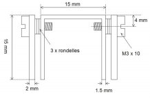
Reference the image below.
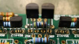
Shown using the red arrows, are 2, 4-pin device holes next to the 2SK devices. What are these used for? The dual equivalent of the JFETs I believe I remember reading in the thread?
Also, show in the images on the HCFR site are silver housings around the USG modules. Are these custom heat sinks of some type, or used for stray RFI.
Attachments

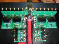
redjr, the heatsinks you saw are not connected to gnd so their use is not for rf shielding but instead these are used to thermally couple all the active devices so in the end you get a lower temperature drift thus a more stable dc offset
Ok. Do they thermally couple just the 2, 2SKxxx devices, or all the BJTs as well. Looks like the layout of the PCB was designed in fact for that? Are these heatsink 'thingies' in the BoM somewhere, or are they user, custom fit if desired? What about the 2, 4-pin devices?
Sorry for the noob questions. I just don't want to screw anything up since this is a very extensive (and pricey) project. 🙂
@group Does someone have a closeup image of the UGS modules fitted with those HS they could share?
Sorry for the noob questions. I just don't want to screw anything up since this is a very extensive (and pricey) project. 🙂
@group Does someone have a closeup image of the UGS modules fitted with those HS they could share?
Last edited:
Ok. Do they thermally couple just the 2, 2SKxxx devices, or all the BJTs as well. Looks like the layout of the PCB was designed in fact for that? Are these heatsink 'thingies' in the BoM somewhere, or are they user, custom fit if desired? What about the 2, 4-pin devices?
Sorry for the noob questions. I just don't want to screw anything up since this is a very extensive (and pricey) project. 🙂
@group Does someone have a closeup image of the UGS modules fitted with those HS they could share?
The 4 pins you highlight belong to the JFET together with the 3 pins in front.
Dual JFET are 7 pins devices.
I am looking to buy the 2SJ74BL and 2SK170BL JFETs at the diyAudio Store
What is the best for the 2 board?
2 x LSK170/LSJ74 ±0.1mA Matched Quad (Grade B)
or
2 x LSK170 ±0.1mA Matched Pair (Grade B) and 2 x LSJ74 ±0.1mA Matched Pair (Grade B)
What is the best for the 2 board?
2 x LSK170/LSJ74 ±0.1mA Matched Quad (Grade B)
or
2 x LSK170 ±0.1mA Matched Pair (Grade B) and 2 x LSJ74 ±0.1mA Matched Pair (Grade B)
Last edited:
@Alex, Just so I"m clear, is this the proper orientation for installing the matched pair of JFETs on each side of the UGS module?
Hi Redjr, in my opinion not.
I never used single JFET as replacement of dual JFET, I only use dual JFET so I cannot share some experience here but when I look at the 2SK389 pinout for example it is - DGS subtrate SGD - so you have to rotate 180 degree one of the single FET you inserted here, probably the right one on the photo I would say (unless we can swap S and D on those JFET which I am not aware of).
I am looking to buy the 2SJ74BL and 2SK170BL JFETs at the diyAudio Store
What is the best for the 2 board?
2 x LSK170/LSJ74 ±0.1mA Matched Quad (Grade B)
or
2 x LSK170 ±0.1mA Matched Pair (Grade B) and 2 x LSJ74 ±0.1mA Matched Pair (Grade B)
It is better to get the second option with N matched together / P matched together.
- Home
- Amplifiers
- Pass Labs
- UGS-muse preamp GB