https://farm6.staticflickr.com/5659/23950428531_d362aa8fbf_o.png
Depending on how much attenuation you use it goes between ~2-3k output resistance and can go as high as 6k. Page 25 in the datasheet has the info.
Ugs input impedance se is 17k and bal 30k. What the muses sees is 17k.
Now without a buffer on ugs output it can be ok or not depending what you want to drive, for sure it won’t be very good driving directly a low impedance and highly capacitive power follower.
If I am wrong please correct me.
https://farm6.staticflickr.com/5659/23950428531_d362aa8fbf_o.png
Depending on how much attenuation you use it goes between ~2-3k output resistance and can go as high as 6k. Page 25 in the datasheet has the info.
Ugs input impedance se is 17k and bal 30k. What the muses sees is 17k.
Now without a buffer on ugs output it can be ok or not depending what you want to drive, for sure it won’t be very good driving directly a low impedance and highly capacitive power follower.
If I am wrong please correct me.
UGSv3 benefint from constant input Z.
Muses-chips varies their output Z.
i think best approach is to use gain (UGS) at first stage, then volume, then buffer.
for me that make the most sense.
as far as overdriving, well... if you can saturate the inputs of some stages you are also (probably) destroying your earings... so...
my2c
Paul does a very nice explanation of output impedance here
Output impedance | PS Audio . After reading you will see that there are 2 buffers needed in this preamp and if correctly understood I think you will know also the correct position for these buffers.
Output impedance | PS Audio . After reading you will see that there are 2 buffers needed in this preamp and if correctly understood I think you will know also the correct position for these buffers.
I just expressed before my preference not to amplify the signal at the input of the muse chip.
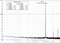
Things to know as well, is that distortion of the UGSbuffer or UGSv3 module depends as well of the signal amplitude they received (see attached spice results).
Hence why it is important to my eyes for not having a too strong analog signal at anypoint within the chain.
Things to know as well, is that distortion of the UGSbuffer or UGSv3 module depends as well of the signal amplitude they received (see attached spice results).
Hence why it is important to my eyes for not having a too strong analog signal at anypoint within the chain.
Attachments

Things to know as well, is that distortion of the UGSbuffer or UGSv3 module depends as well of the signal amplitude they received....
... is not true for every piece of audio equipment ? bigger signal ➡ bigger distortion.
i think the most crucial thing to keep under control is the impedance that the ugs module sees at its input. must be as costant as possible hence. the muse chip varies output impedance... so, i personally will not put the gain stage after the volume. but rather, in front.

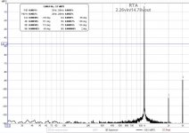
I don't like that H3 is higher than H2 but the overall distortion is so low that it shouldn't be noticeable.
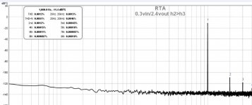
Well...I can tell you one small secret, I actually can adjust h2 vs h3
i guess is all a matter of balancing current between the N-ch an P-ch fets
DC offset ?Well...I can tell you one small secret, I actually can adjust h2 vs h3
I just expressed before my preference not to amplify the signal at the input of the muse chip.
Things to know as well, is that distortion of the UGSbuffer or UGSv3 module depends as well of the signal amplitude they received (see attached spice results).
Hence why it is important to my eyes for not having a too strong analog signal at anypoint within the chain.
btw... if i am not totally mistaken, i was reviewing the schematic and seems that the preamp follows this very routing.
with two ugs module, first it gets "amplified" then it goes to the muse volume controller and at last, inserts in the buffer before exiting.
and that make the most sense to me
The schematic only shows that a UGS module can be placed in either M1 or M2 socket.
There is no distinction made between buffer and UGS module within the schematic.
I am not as concerned as yourself by the output impedance presented by the Muse.
For me it is a false problem assuming the muse output impedance remains constant at a given attenuation level.
Overall chain distortion is what I tried to address (easy to compare if you take as an example a 1v signal in and 1v signal out and you place the gain stage before or after the attenuator).
But let's close the debate for now. When you get your preamp build, you can try both solutions and check/measure by yourself which one you prefer most and/or provide you with the best thd results.
in the schematic is reported where to put what (see attached). and from what i see M2 is before the Muse chip and M1 is after.The schematic only shows that a UGS module can be placed in either M1 or M2 socket.
There is no distinction made between buffer and UGS module within the schematic.
I assume that is the "default" positions, and nothing prevents you to swap them, sure... but i guess there's a reason behind the decision to have the gain module in front and buffer as output.
Sure i will... I can not wait to start assembling it...When you get your preamp build, you can try both solutions and check/measure by yourself which one you prefer most and/or provide you with the best thd results.
Attachments

Actually, none I could think of except to favor the muse chip to operate with greater signal amplitude. This is OK but beware if your external source delivers high signaling level.but i guess there's a reason behind the decision to have the gain module in front and buffer as output.
Small gain mismatch does that in differential mode.Well...I can tell you one small secret, I actually can adjust h2 vs h3
Actually, none I could think of except to favor the muse chip to operate with greater signal amplitude. This is OK but beware if your external source delivers high signaling level.
the muse has enough headroom to handle the ugs @ maximum level... so i guess is electrically safe. Must check thd...
in theory i still prefer to have the ugs gain stage to performs coherently throughout the attenuation steps...
we'll see

do we have a date for closing?
is a never ending stoooooryyyy..... stoooorrryyyy
- Home
- Amplifiers
- Pass Labs
- UGS-muse preamp GB