Thank youHi, Randy and all
Here I upload below DXF files together for reference.
1. Main PCB dxf
2. I/O board dxf
3. Neutrik XLR-Female dxf
Thanks,Eric
The chassis model for the Eric1 HS is ready


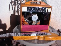
The chassis is symmetrical top to bottom, side to side and front to back. All components, terminals and boards attach to the inlay panels. The chassis is finished by wrapping in a choice of material. My versions will be wrapped in blue, red or black fabric and stitched
All the inlay panels attach via internal M4 screws into threaded holes from the inside except for the base inlay which is screwed from the outside and as it is under the chassis it leads to a fastener free looks
All the inlays have an overall thickness of 6mm to allow for some intricate lamination and light effects
For this chassis, I have gone directly from MAD to CAD without drawing a GA as even my kid can make out what goes where
I am thinking about making this 25mm longer and offsetting the top inlay back by that much. This is to create a pocket behind the face inlay for other electronics like a pre
Like so

This is the extended version. Everything else remains the same. The two part labels are:
Chassis Eric1
Chassis Eric1ext
Next task, design and make the base inlay. Secure the Eric1v3 amp board and the power cable and finally able to do some testing
This is the extended version. Everything else remains the same. The two part labels are:
Chassis Eric1
Chassis Eric1ext
Next task, design and make the base inlay. Secure the Eric1v3 amp board and the power cable and finally able to do some testing
Baseplate will have a 40x40x7mm fan
This one is attractive for price, size and quietness rating
https://www.aliexpress.com/item/324...210318be16674569587008984e5985!66461976311!sh
Rated voltage: DC 12 v
This one is attractive for price, size and quietness rating
https://www.aliexpress.com/item/324...210318be16674569587008984e5985!66461976311!sh
Rated voltage: DC 12 v
Current rating: 0.1 A
Power consumption: 1.2 W
Noise: 15 dBA
Revolution: 5200 + 10% RPM
I agree. I think some of this is based on conservative customer preferences. Most of the vehicles I see on the road these days are white, black, or some shade of grey.A web search for amplifiers brings up industrial or lab look in the industry. Usually hard silver or black units. This is so boring, everything really looks much like everything else. Whether in hi-fi or pro audio.
I'd be tempted to say these are boring colours, but it's even worse than that. Strictly speaking, black, white and grey aren't even really colours at all!
Black is the absence of all light (i.e. it is no colour at all).
White is the sum of all visible colours, so it's not a (single) colour, either.
That leaves grey. It really isn't a colour, either. It's what's left if you strip the actual hue (colour) out of something - all you have left is what artists call "value", i.e a patch that is neither bright nor dark, but in-between. Boring, depressing grey.
How did we end up with such incredibly drab automotive paint colours?

I don't know, but I guess the statistics tell the tale - presumably auto manufacturers know they will easily find buyers for these drab and conservative paint schemes. And having only 3 boring colours must help reduce inventory.
Speaking of conservative customers, some years ago Fender made a run of their little Frontman 25R guitar amps, upholstered in bright holly-berry-red Tolex. These appeared on the market just before Christmas, and I expect the red theme was intended to make them sell well as Christmas-morning presents under the tree.
Not long after Christmas, Guitar Center dropped the price on these quite a lot. I guess they didn't sell as well as Fender had been hoping. Most male American guitarists I've met would be very uncomfortable using a bright red guitar amplifier.
It was before my time, but it seems to me that North America wasn't always this uncomfortable with colour. Just look at those mid-fifties American cars and trucks that came in all sorts of shades, from aqua (blue) to aquamarine (blue-green) to coral (pink).
I recently bought an aqua MI amplifier ( https://www.amazon.com/Coolmusic-Acoustic-Amplifier-Portable-Bluetooth/dp/B09DYKHNML ). It was substantially cheaper than the otherwise-identical black version, probably because most musicians in this part of the world are too conservative to buy a blue amplifier, so the marketers dropped the price of the blue version in North America.
I recently stumbled across a Web article about Leo Fender's earliest Fender-branded guitar amplifiers, dating from 1946.So many are trying to make their guitar amp or Bluetooth speaker look like a Marshal.
You might like the look: they are made of beautifully contoured and finished solid wood, with colourful grille-cloth: https://www.fender.com/articles/gear/the-woodies-a-history-of-fenders-first-amps
Good luck with your project!
-Gnobuddy
Hey good to hear from you. Thing is that I don’t see colour as an ‘option’. Colour thrown on something that was made to look good in will always end up looking tacky
Colour is a major input for a major sense. It really needs to disappear in the object, I find this concept difficult to explain. If the use of colour looks like dressed up then the designer has failed miserably
The only impression should be on the beholder is that only the finest belongs on this baby. That such a figure was given all the respect and attention it deserves
Colour is not as simple as splash and dash. The figure had to be able to take that colour and the designer has to be able to see how much of what colours show which feature off
Firstly colour needs a figure that can wear it. Secondly, colour own it’s own cannot work as it’s an items signature so it needs to follow tone paths and be properly terminated by the use of other tones and textures. Lastly, colour needs a theme. Without this the other two requirements cannot be made to marry
As an example, a decorative wood panel on an aluminium chassis for an amplifier. Think about why the wood is usually chosen as a face. The problem with aluminium is that we know it’s a metal so the only appearance that appears to show off the best features of that material is a metallic crystal one from anodising. Colour doesn’t work here at all. Only the metal tones of various silvers and gold or darkening works. The only way to get an appealing colour finish on aluminium is to use PVD or layering. So wood is chosen with the belief that it will be easier to look pretty. Guess what, the results that I have seen everywhere still looks like a bit of wood stuck on and says “hey look, I also used wood because I thot it would be easier to look pretty “
What makes the wood appealing? It’s has colour tones and textures. What makes it look like a bit of wood stuck on. Utter failure to contemplate how to flow and terminate the very limited possibilities available in wood. Unless the poweamp is being built into furniture or sculpture, wide expenses of wood actually doesn’t appear to belong and only suitable as a trim material
Attention should be payed to the point that I made about the difference in the culture of appearance of the objects that produce the sound and the objects that reproduce the sound. As I observed, the actual guitar, drums and other instrument makers have nailed figure, flow and theme. But the when it comes to designing the electronics, it’s a black box
The hope is to use what I know of implementing colour and aspire to place some products for those like me that enjoy to drink with their eyes too
Additional to above regarding wood faced hi-fi amplifier. How to make wood work, as much as the idea that wood can be rounded and contoured and stained and finish applied and all that. Well, not going to look good. That's where anyone actually hoping to end with an attractive result and not just a piece of prettied wood stuck on really need to get their MAD engaged
Were I to make a wood panel for an aluminium chassis, my MAD constraints would be:
Figure
Aluminium chassis is very angular. Box shape is very angular. I can't apply contoured wood, it will look bad. What looks good in MAD and can be executed with fine detail to so that the metal figure looks have been given respect and attention and the beholder is given the impression that it's an all around fine beauty. My answer is very a very hard and square edged wood face slab that is not too thick. Anything thicker than 10mm is too thick and changes metals perspectives in a bad way. Shave it down! Don't touch the edges, don't cover the edges. Cut oversized and grade sand it down to get clean hard sharp edges free from any blade whirls and scratches. If this is not done than it makes the whole result looks bad
Flow
When the base figure is hard and boxy, contouring the edges may seem to the mind to soften it, but it makes it look bulky and badly made. Soften the expenses by using pretty bits and using the wood to terminate them. A large volume knob made from the same wood fitted into a cutout and the face wood terminating its circle along its length is the best way to add a softening tone to the wood slab and angular body. If you take that or any other knob and put it on a shaft coming up through the wood, then it looks like a knob sitting on a shaft coming up through the wood. The knob circle needs a proper termination and is very slack of designers to inflict this pain on the eyes of those who chose the product for other features. Not all poweramps have volume controls, so what else can I do? I can fit a bezel that correctly terminates a power switch and use a switch that will soften the hard case and face. This is the place for circles and rounded corners!
Don't use wood if you are not going to work on it with correct components like the right sanding. If a filler minimum spec Feast Watson sanding filler is not used, don't put the wood as decoration. I have made my own formulation that I find gives better results then Feast Watson so if a silly taxi driver can do it then so can the experts here. The initial boxes that I made for speakers for Uffornica were done when I was limited to box shapes. The boxes have both contours and hard edges. The contours are sanded to show the shine and tone from within the wood, and the hard edges are knife-edge sharp. The contours are not used anywhere on terminating edges but rater on the top and bottom of the face where it has to flow onto something organic and stays within the visual expense of the wood
Theme
Build a theme, marry the wood to other areas with more little bits of wood. Knobs, feet layers, handles and trims are areas where the wood can be used to build a theme. It will look lonely unless another theme was built for terminations like bezels, buttons and lights
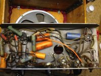
Ugly inside.earliest Fender-branded guitar amplifiers
Attachments
Base inlay design done. The inlay replaces the need for a baseplate. The Eric1v3 board mounts inverted, fins down. The fan pocket can be seen and draws air in from the outside. Exhaust slot can also be seen. Both ventilation slots will feature filtration screens
The board mounts on the standoffs and clears the base by a mil. PCB standoffs can be mounted over and a screening plate fitted
Now that the design is ready, I am ready to make the first part 🙂


The board mounts on the standoffs and clears the base by a mil. PCB standoffs can be mounted over and a screening plate fitted
Now that the design is ready, I am ready to make the first part 🙂
I think it's fascinating how the appearance of a technology changes as it matures.Ugly inside.
Early electronics looked like wooden furniture on the outside (and a rat's nest inside).
Early automobiles looked like horse-drawn carts and carriages.
Interestingly, the turret-board layouts so beloved by DIY and boutique tube amplifier builders are technically one of the worst ways to build a circuit. Placing dozens of components side by side in a long row, and then running many inches of wire to large numbers of them, creates a vast mess of stray capacitances and accidental signal couplings.
It's a wonder any of these builds are usable as amplifiers at all. One would expect them all to be oscillating at radio frequencies.
Leo's ugly-inside 1946 amps would have been a nightmare to repair, but probably less prone to parasitic capacitances and unwanted oscillation than his later turret-board based builds.
Switching to much later Fender PCB designs didn't help that much, probably because of the amount of cost-cutting in the designs (no grid stopper resistors, etc). I've owned three Fender tube amplifiers (Super Champ XD, Blues Junior, '65 Princeton Reverb reissue), and all three left the factory on the hairy edge of full-on RF oscillation.
The Blues Junior was the worst of the lot. It would burst into oscillation after an output tube swap, until you moved the ribbon cables running to the EL84 sockets to their happy place with chopsticks. It would burst into oscillation if you clipped the ground wire of a DMM to the chassis. It would burst into oscillation if you put an external guitar FX pedal on the floor within a metre of it.
-Gnobuddy
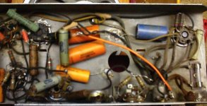
A bit of a serious wanting to learn type question to you and others, have a look at the linked video below. I have been doing some electronics like that. Just like a laid out schematic and soldered tidy like that. No PCB and tracks made from stiff single core tinned wireI think it's fascinating how the appearance of a technology changes as it matures.
Early electronics looked like wooden furniture on the outside (and a rat's nest inside).
Early automobiles looked like horse-drawn carts and carriages.
Interestingly, the turret-board layouts so beloved by DIY and boutique tube amplifier builders are technically one of the worst ways to build a circuit. Placing dozens of components side by side in a long row, and then running many inches of wire to large numbers of them, creates a vast mess of stray capacitances and accidental signal couplings.
It's a wonder any of these builds are usable as amplifiers at all. One would expect them all to be oscillating at radio frequencies.
Leo's ugly-inside 1946 amps would have been a nightmare to repair, but probably less prone to parasitic capacitances and unwanted oscillation than his later turret-board based builds.
Switching to much later Fender PCB designs didn't help that much, probably because of the amount of cost-cutting in the designs (no grid stopper resistors, etc). I've owned three Fender tube amplifiers (Super Champ XD, Blues Junior, '65 Princeton Reverb reissue), and all three left the factory on the hairy edge of full-on RF oscillation.
The Blues Junior was the worst of the lot. It would burst into oscillation after an output tube swap, until you moved the ribbon cables running to the EL84 sockets to their happy place with chopsticks. It would burst into oscillation if you clipped the ground wire of a DMM to the chassis. It would burst into oscillation if you put an external guitar FX pedal on the floor within a metre of it.
-Gnobuddy
I'm going to be quite direct with my answer, because I think it's important to look at this seriously.electronics like that...a laid out schematic...No PCB and tracks made from stiff single core tinned wire
<snip>
What would be the problems of doing a simple tone or pre circuit in this manner?
Let's ask ourselves the following questions:
1) What happens if you pick up the completed circuit, hold between finger and thumb, and shake vigorously five times? Will it still work after that?
2) What happens to the circuit if you pack the completed circuit into a suitcase, with clothes and books and razors and hair-brushes all jammed around it, check the suitcase in at the airport, and then pull it out at your destination, three flights and four airports later? Do you think it will still work?
3) How many times can you operate the push-buttons before the soldered joints and switch lugs develop metal fatigue and crack?
4) What happens if those free-hanging copper wires intermittently touch each other when you adjust the volume, while your preamp is feeding a signal to a 50W power amplifier? How long before the explosively loud bangs and thumps destroy your loudspeakers and damage your hearing?
I think you can see where all this is leading.
A circuit built like that is a bit of crude unskilled folk art, suitable for framing or hanging on the wall, if it happens to suit your tastes.
It is not a useful or usable electronic device.
Our world has been dumbed-down a lot in recent decades. We are over-exposed to pretty or exciting visual things, and under-exposed to intellectual concepts that are not visually pretty or exciting. But those not-pretty things are actually far more important to the continuation of civilization as we know it.
Many of us have completely forgotten this now. We have been conditioned and dumbed-down to think pretty is always better.
Electronics is a type of engineering. Engineering that doesn't actually work, which can't stand up to its normal intended use, is a failure. A joke. An embarrassment.
Making things pretty doesn't make them better if it makes them useless for their intended purpose. It makes them worse.
An ugly bridge that doesn't collapse is a better bridge than a pretty one that falls into the river on the first windy day.
Ugly steel control arms smeared with black grease hold your front wheels on better than polished wooden control arms would. The pretty wooden arms would break the first time your tyre hits a pothole, and you would have an accident. The ugly steel control arms get you home safe and sound.
Electronic devices made with components firmly mounted to a PCB, housing, or turret-board, and no physical strains applied to solder joints, are much better than devices made with unsupported parts dangling in thin air, with weak copper wires, and even weaker solder joints, running between them.
If you enjoy creating folk visual art using electronic components, sure, make 3D pictures with carefully bent copper wire. Hang them on the wall when you're done. They're visual art, not usable electronic devices. Nothing wrong with that, if visual art is what you're after.
On the other hand, if you want to actually create a working electronics device, use the various construction techniques that have been developed over the last century, in order to create reliable and usable products.
One absolutely fundamental key factor is to make sure that all components are strongly and securely supported, most particularly components that will also be handled by the user (switches, knobs, etc).
A second key factor is to enclose the delicate parts, to protect them both from mechanical intrusion, and from ingress of dirt, dust, moisture, et cetera.
It's certainly possible to create an electronic device that's both functional, and good-looking. But you won't get that result with fragile exposed solder joints and fragile copper wire making a rats nest of unsupported components in mid-air.
-Gnobuddy
Ah, a bit unsupported then!
But then is something wrong with the PCB method? My volume control and power switch on a shop bought amp are PCB mounted and bad joints on three separate units. I wonder if they would have been more reliable had the joint been longer and softer
You see, I find the idea of PCB based channel strips attractive for build simplicity, but I also worry about the durability of so many PCB mounted pots and switches. I am tempted to invent a hole new way of doing this
Problems! Two days ago we had finally assembled this giant 3D printer and had issues. Instructions from the manual and YouTube were rubbish. My unit kept shuddering and erroring during auto levelling. After much tracing the machine, it turned out that the gantry couplings were locked in with a pair of gantry screws that had been backed out to rest the edge of the screw head into the coupling grooves. I think it is reasonable to assume that this important detail would have been mentioned
For a test print my daughter wanted a dice for a snakes and ladders. I taught her how to model one and we sliced it using the latest stock slicer. Wouldnt print. Error messages. Instead of the latest slicer, I tried slicing with the stock print suited program and that worked first time. Very nice print on default settings
I noticed that the print application was very laggy in use but I am on a Samsung i7 lapptop with 8gb ram. With the successful test print, decided to print the Base inlay for the amp. Checked the settings then hit slice, bang! Not really bang but the laptop shutdown and wouldn’t start. Screen lights up and fan runs but that’s it. Can’t bring up bios or recovery. A few days earlier my wifes laptop had also played up and gotten stuck on the splash screen boot loop and again cannot bring up any recovery tools. So now have bought a refurbished i5 6500 3.2ghz with 8gb ram and hopefully be here in a few days. Why i5 6500? So I can give windows 10 on it the boot and install windows 7. Hopefully will be able to get a new Mac mini in the near future as I just can’t seem to be able to get anything done with windows 10
Bigger problem. I lost all my CAD files for Uffornica and this amp including the Base inlay that I was about to slice. Now will have to extract the SSD from the old laptop and try to recover my user folders. I had my folders set to sync with google drive but had not noticed that the cloud storage had been full some time ago with my music library. Had not realised that even the latest additions to the music library had not been able to sync. Luckily all my very difficult to source DJ versions of reggae singles are safe in cloud as well as my extensive collection of old gold Indian songs. I worked in data security for 10 years back in the days and left the industry to start my own fishing tackle manufacturing business when cloud loomed and looked set to uber the data security industry. I must say that cloud has made small user data security very accessible to the end where I have just purchased a larger iCloud account so I may keep all my important work files safe going into the future
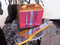
With our computers out of commission, there isn’t too much that I can do over the next few days so will take that opportunity to work on a pair of solid birch speaker boxes that I glued up almost a year ago but passed on over a better box method. It’s a shame to waste these boxes so I have given them a quick and dirty version of my wood prep routine and finished them in a slightly darkened patina. They look good but I am still not happy. I will strip and try a further darkening process. I don’t use standard wood finishes as I have extremely high standards for finished wood
Looks like I will have to hook up my iPhone to the big screen to work on the photos so I am off to pick up a lightning to hdmi dongle. Will post some pics of these speaker boxes once that is sorted. The drivers took almost 3 years of searching and auditioning before I was happy with the sounds reaching my ears. A very interesting pair of 6.5” coaxial with silk dome tweeters and f3 30hz and very low efficiency. They can be spotted on the desk with the bare speaker boxes earlier in this thread
For a test print my daughter wanted a dice for a snakes and ladders. I taught her how to model one and we sliced it using the latest stock slicer. Wouldnt print. Error messages. Instead of the latest slicer, I tried slicing with the stock print suited program and that worked first time. Very nice print on default settings
I noticed that the print application was very laggy in use but I am on a Samsung i7 lapptop with 8gb ram. With the successful test print, decided to print the Base inlay for the amp. Checked the settings then hit slice, bang! Not really bang but the laptop shutdown and wouldn’t start. Screen lights up and fan runs but that’s it. Can’t bring up bios or recovery. A few days earlier my wifes laptop had also played up and gotten stuck on the splash screen boot loop and again cannot bring up any recovery tools. So now have bought a refurbished i5 6500 3.2ghz with 8gb ram and hopefully be here in a few days. Why i5 6500? So I can give windows 10 on it the boot and install windows 7. Hopefully will be able to get a new Mac mini in the near future as I just can’t seem to be able to get anything done with windows 10
Bigger problem. I lost all my CAD files for Uffornica and this amp including the Base inlay that I was about to slice. Now will have to extract the SSD from the old laptop and try to recover my user folders. I had my folders set to sync with google drive but had not noticed that the cloud storage had been full some time ago with my music library. Had not realised that even the latest additions to the music library had not been able to sync. Luckily all my very difficult to source DJ versions of reggae singles are safe in cloud as well as my extensive collection of old gold Indian songs. I worked in data security for 10 years back in the days and left the industry to start my own fishing tackle manufacturing business when cloud loomed and looked set to uber the data security industry. I must say that cloud has made small user data security very accessible to the end where I have just purchased a larger iCloud account so I may keep all my important work files safe going into the future
With our computers out of commission, there isn’t too much that I can do over the next few days so will take that opportunity to work on a pair of solid birch speaker boxes that I glued up almost a year ago but passed on over a better box method. It’s a shame to waste these boxes so I have given them a quick and dirty version of my wood prep routine and finished them in a slightly darkened patina. They look good but I am still not happy. I will strip and try a further darkening process. I don’t use standard wood finishes as I have extremely high standards for finished wood
Looks like I will have to hook up my iPhone to the big screen to work on the photos so I am off to pick up a lightning to hdmi dongle. Will post some pics of these speaker boxes once that is sorted. The drivers took almost 3 years of searching and auditioning before I was happy with the sounds reaching my ears. A very interesting pair of 6.5” coaxial with silk dome tweeters and f3 30hz and very low efficiency. They can be spotted on the desk with the bare speaker boxes earlier in this thread
Oh, man. I feel for you. Ugh. 🙁Problems!
Linux is a wonderful rescue tool in this sort of situation.Bigger problem. I lost all my CAD files for Uffornica and this amp <snip>
...will have to extract the SSD from the old laptop and try to recover my user folders.
If your laptop hardware is still working (and it's Windows that died), you can boot from a Linux USB drive, find your folders on the internal SSD, and make copies to an external USB drive.
Fingers crossed, the SSD itself is intact, and so are your data files.
I agree with you about Windows 10 being one giant piece of garbage. It's more spyware than operating system.
-Gnobuddy
The old rule used to be never to depend on solder to provide mechanical fastening, only an electrical connection.But then is something wrong with the PCB method? My volume control and power switch on a shop bought amp are PCB mounted and bad joints on three separate units. I wonder if they would have been more reliable had the joint been longer and softer.
It is possible to mount switches and pots on a PCB, carefully spaced so that you can drop a suitably drilled front panel over the whole thing, and use nuts to fasten all the switches and pots to the front panel. This can be very reliable, the only catch being that you have to get all the holes in the right places for everything to fit.
(Often it's easier to mount all the parts to the panel first, before soldering. Then offer up the PCB to the rear of the panel, wiggle it onto all the leads, and finally solder the joints.)
Another similar possibility is to mount all the controls (pots/ switches / indicator LEDs) to a sub-PCB, which mounts to the front panel as above. Then you run one or more ribbon cables from the sub-PCB to the main PCB.
There are some shoddy brands (cough Behringer FX pedals cough) which do away entirely with the mechanical fastening, leaving only the solder joints to cope with mechanical stresses. Unsurprisingly, input and output jacks tend to fail quite quickly, as the solder joints fail under the large mechanical stresses.
There is plenty of reliable PCB-based audio equipment out there, which you can take a look at to see how it was done.I am tempted to invent a (w)hole new way of doing this
I understand the temptation to invent a new method, but reputable companies have had decades of experience with tens of thousands of warranty claims, so they know more about oddball failure mechanisms than you or I can expect to figure out on our own.
-Gnobuddy
New PC installed! Finally back online properly, hate doing this on a device. Windows 10 seems to be behaving so far. I do miss some of the more user-friendly stuff from Windows 7 like easy access to settings and things, and I think I might do a dual boot. Use 10 only for programs like Blender that don't install on 7
Hey man
Do you have a link to a USB boot file that you know to work well? I really haven't kept up with laptop tech over the last 10yrs or so still need to figure out how to get to the storage on the old laptop and get my 3D files amongst other important things
Oh, man. I feel for you. Ugh. 🙁
Linux is a wonderful rescue tool in this sort of situation.
If your laptop hardware is still working (and it's Windows that died), you can boot from a Linux USB drive, find your folders on the internal SSD, and make copies to an external USB drive.
Fingers crossed, the SSD itself is intact, and so are your data files.
I agree with you about Windows 10 being one giant piece of garbage. It's more spyware than operating system.
-Gnobuddy
Hey man
Do you have a link to a USB boot file that you know to work well? I really haven't kept up with laptop tech over the last 10yrs or so still need to figure out how to get to the storage on the old laptop and get my 3D files amongst other important things
My go-to is Xubuntu 20.04, though there are plenty of others that will do equally well. There's even a download server in Australia for your convenience.Do you have a link to a USB boot file that you know to work well?
Here's a link: https://xubuntu.org/release/20-04/
Direct link to the server in Australia: http://mirror.aarnet.edu.au/pub/xubuntu/releases/20.04/release/
The file you want to download is "xubuntu-20.04.5-desktop-amd64.iso"
Once downloaded, you'll need to create a bootable USB drive using this file. I assume you'll be doing this on a Windows PC. This 2021 tutorial might work for you: https://linuxize.com/post/how-to-create-a-bootable-ubuntu-18-04-usb-stick/
I say "might", because I loathe Windows, and avoid using it whenever possible, so I haven't actually created a bootable Linux USB drive using a Windows PC myself.
Once you get your laptop to boot from the Xubuntu thumb-drive, the rest of the process should be pretty straight forward. I think Xubuntu even auto-sniffs other drives on the computer, and auto-mounts them to the desktop.
At that point all you have to do is click on these drive icons on your desktop, one at a time, until you find the one that holds all the files from your laptop. Once you find it, you can copy (drag and drop) those files over to another USB drive, or an external SSD, or whatever backup device you prefer.
You will probably find your files in a sub-folder named "User\RBassinga\", or whatever your Windows username is.
This tutorial (using a different flavour of Linux) might be helpful: https://www.thewindowsclub.com/recover-windows-files-with-linux-live-cd-usb
With Xubuntu and other Ubuntu-based versions of Linux, there is even a built-in rescue tool that lets you copy files over your computer network. Basically you can start up a simple file server and point it at the files you want to make available, and then access them over your home network from any other PC, so you can copy them to whichever computing device you want. This is very useful if you need to copy one single file onto multiple PCs.
For your purposes, plugging in an external USB drive and dragging and dropping files to it is probably the easiest way to go.
There are a lot of things I like about Linux, and this ability to save precious files after Microsoft's abomination has failed to boot, is one of them. Twice now I've been fortunate enough to have been able to rescue priceless family photos for friends or co-workers, after their Windows PC fails to boot, and they realize with horror that ten years worth of photos of their babies growing up are now gone for good - and they have no backups at all.

(Fortunately, not for good, because in both cases the actual files were fine. It was only the Windows OS that had massively messed itself up, and could no longer boot.)
-Gnobuddy
Thanks man. I went to the local IT shop and asked about copying the user folders from the SSD and was quoted $300. I'll use the links you provided, hoping for the best
- Home
- Live Sound
- Instruments and Amps
- Uf'fornica Homestage - concept, design and build log