Hi,
If you keep hunting around you'll find some diagrams that may be sort of similar in nature to UcD.
The op amp portion has, I believe, a linear type voltage regulator, the discrete comparator portion has current source and active current mirror load. There's little doubt a tightly regulated supply would improve things (when won't it) but doesn't seem to be a necessity. Up to you really.
Caps would make a difference of course and there's endless discussion on it as you've seen.
I trust when you say "due to the effect they have on vulnerable digital and oscillator circuits." regarding the PSU caps you're refering to PSRR? That's just a matter of sizing them properly.
ESR is the bigger concern, since it is directly in path with the load. Low ESR across across the audio band would be very nice.
As far as the oscillator goes, self oscillation is an extremely robust way of going about it that does away with things like jitter (no clock), and other timing errors (dead time and usual delays), as they become an intrical part of the oscillation/feedback loop.
Maybe someone else can tell you more about the PSRR of it, was surprised to see it wasn't on the data sheet, or maybe I just missed it?
Hope that helps you a little bit.
If you find the link to the patent info that'll help you a bit too, makes for good reading! I lost all my links so.. It's here someplace.
nickywicky said:
I'm pretty sure the problem will come down to one faulty module. I have 3 modules; one had no EMI problem, one had a small issue but the ferrite sleeves did solve that one. The 3rd one can even have the speaker cable to the module totally disconnected (so there is no speaker cable) and be inside a metal case and still creates EMI. We'll have to wait for the shipping time from NZ->Netherlands for confirmation of this though.
This problem has now been diagnosed and fixed by Hypex. I had a loose screw so that the T-sink was floating. The T-sink is normally connected via a 100nF cap to 0V.
So thanks Hypex for fixing this and my blown-up module.
😎
nickywicky said:
This problem has now been diagnosed and fixed by Hypex. I had a loose screw so that the T-sink was floating. The T-sink is normally connected via a 100nF cap to 0V.
So thanks Hypex for fixing this and my blown-up module.
😎
Thanks for that update. Neat trick! Hard to believe it would make such a dramatic difference. Next we'll be seeing amps built around a bypassed "8" sink 🙂

nickywicky said:
This problem has now been diagnosed and fixed by Hypex. I had a loose screw so that the T-sink was floating. The T-sink is normally connected via a 100nF cap to 0V.
So thanks Hypex for fixing this and my blown-up module.
😎
And for the final update on this subject; I have now received the modules and tried them out. Perfection. No interference at all.
😀
And thanks Jan Peter for the present of 3 ferrite sleeves in my package. This was an unexpected surprise. But it makes me wonder about how to use these ferrite clamps. I was using six, one for each speaker cable (3 modules). Should I have been using just 3 ferrires and squeeze the two speaker wires from each module through just one of them ?
( There's no interference so I cannot investigate this now.)
Nickywicky ,
I am glad the problem is solved now 😀
If you like do decrease the EMI by +/-10dB you can use the Ferrite Clamps, it's only necessary to use them on the speakercable.
Good luck with your modules!
Regards,
Jan-Peter
I am glad the problem is solved now 😀
If you like do decrease the EMI by +/-10dB you can use the Ferrite Clamps, it's only necessary to use them on the speakercable.
Good luck with your modules!
Regards,
Jan-Peter
Hansen,
What's ELFA???
They looks like this;
http://nl.farnell.com/productimages/farnell/standard/FS176.LR.jpg
http://nl.farnell.com/jsp/endecaSearch/partDetail.jsp?SKU=535898&N=401
Regards,
Jan-Peter
What's ELFA???
They looks like this;
http://nl.farnell.com/productimages/farnell/standard/FS176.LR.jpg
http://nl.farnell.com/jsp/endecaSearch/partDetail.jsp?SKU=535898&N=401
Regards,
Jan-Peter
Thanks for the picture. It seems to be something like this
http://www.elfa.se/elfa-bin/dyndok.pl?dok=2011482.htm
or
http://www.elfa.se/elfa-bin/dyndok.pl?dok=2011483.htm
or the non-clamped
http://www.elfa.se/elfa-bin/dyndok.pl?dok=2011488.htm
I guess a small ferrite ring with the wire looped once through it would also do.
http://www.elfa.se/elfa-bin/dyndok.pl?dok=2011482.htm
or
http://www.elfa.se/elfa-bin/dyndok.pl?dok=2011483.htm
or the non-clamped
http://www.elfa.se/elfa-bin/dyndok.pl?dok=2011488.htm
I guess a small ferrite ring with the wire looped once through it would also do.
line input
The JeffRowland 201 amps use a Lundahl LL 1545 line input transformer right in front of the ICEpower 500ASP module. Does it make sense to try something similar with the UCD modules? Anybody have any experience?
The JeffRowland 201 amps use a Lundahl LL 1545 line input transformer right in front of the ICEpower 500ASP module. Does it make sense to try something similar with the UCD modules? Anybody have any experience?
Halfway done
Hi.
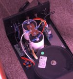
After having a pair of UcD400AD laying around for months I finally managed to find time to assemble one monoblock. I completed the first one because I wanted to hear it of course -- now I just need to find a day to build the other one 🙂
Having only one channel so far I can't/won't comment on the sound quality yet, but the channel I have so far has abolutely no audible noise or other things that should not be there.
Components:
LC Audio soft start module
TransTEC 800VA 40-0-40 V potted transformer
Regular 35A rectifier bridge with 4 100nF/250V soldered to it
RIFA 22000uF/100V beer-can sized caps 🙂
UcD400AD module
By the way: How the f... do I solder the wires from the UcD module to the speaker terminals. No matter how long I heat them the solder wont bond. (That's why you see two ugly screws holding wires in the speaker-terminals)
Photo attached. Sorry for the weird purple lighting. The photos are shot in the evening and only lit by two 7W energy saving bulbs that seem to emit a weird light when cold.
Hi.
After having a pair of UcD400AD laying around for months I finally managed to find time to assemble one monoblock. I completed the first one because I wanted to hear it of course -- now I just need to find a day to build the other one 🙂
Having only one channel so far I can't/won't comment on the sound quality yet, but the channel I have so far has abolutely no audible noise or other things that should not be there.
Components:
LC Audio soft start module
TransTEC 800VA 40-0-40 V potted transformer
Regular 35A rectifier bridge with 4 100nF/250V soldered to it
RIFA 22000uF/100V beer-can sized caps 🙂
UcD400AD module
By the way: How the f... do I solder the wires from the UcD module to the speaker terminals. No matter how long I heat them the solder wont bond. (That's why you see two ugly screws holding wires in the speaker-terminals)
Photo attached. Sorry for the weird purple lighting. The photos are shot in the evening and only lit by two 7W energy saving bulbs that seem to emit a weird light when cold.
Attachments
Nice work,
Maybe there's some sort of coating on it to keep it from oxidizing. Try scrapping them with a knife and sand them a bit, tin, solder, should work better.
Maybe there's some sort of coating on it to keep it from oxidizing. Try scrapping them with a knife and sand them a bit, tin, solder, should work better.
Context
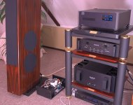
Another photo of the lonely monoblock. This time showing the hardware it is connected to (dont worry, I tested the amp first with an old cheap bookshelf speaker 🙂.
Still the image quality problem: I fiddled with the white balance adjustment etc. but the sick purple light just wont to away completely. Besides that the photo seems nice and sharp.
By the way: Isn't there an LED on the UcD400 module? I dont see anything lighting up, and still it plays like it is supposed to.
Damn I'm looking forward to having completed the other channel also 🙂
Given the flexibility of monoblocks, what is preferrable: Close-to-speaker placement with short speakerwires and longer (balanced) interconnect or longer speakerwires and short interconnect?
Attachments
Re: Context
That's my preference.hansen said:Given the flexibility of monoblocks, what is preferrable: Close-to-speaker placement with short speakerwires and longer (balanced) interconnect
So whats the verdict
I want to buy either the UcD400 or the zapulse 2.2, but my main concern is sound quality. My preference is treble, and clarity not so much with bass.
Could anyone who has compared the two tell me which is best?
Right now I think I might go for the UcD but I want to be sure that I make the right decesion.
BTW will +/-80VDC be too much for the zapulse?
Thanks
Lawrence
They both work out to about the same price, and both are excellent. My choice for sound quality would be for the UCD400 by a small margin.
80v is too much for either of these modules though. I think you want something like 62v dc max? However, I also seem to remember reading that the input specs on one of the modules had been lifted quite a lot (perhaps to 80v?), but you would need to check the details yourself...
80v is too much for either of these modules though. I think you want something like 62v dc max? However, I also seem to remember reading that the input specs on one of the modules had been lifted quite a lot (perhaps to 80v?), but you would need to check the details yourself...
What do I need?
Hi guys,
I know it has been asked before and the info is scattered in many posts but somehow I can't manage to collect the right info so some help on this topic is very much appreciated.
I am building a high end sealed sub and I want to use the UCD400 for amplification. I don't mind spending a bit more if I get quality and a nice solution.
I've been looking at PS boards from Schuro and LC Audio and of course the DIY variants that come along in the posts.
Can somebody advise me on the following parts list?
1) UCD400 - no brainer
2) LC Audio Soft start unit > Do I need one ?
3) LC Audio DC Filter > Do I need one ?
4) IEC Inlet with fuse and noise filter > what fuse rating / current rating do I need ?
5) Amplimo or Shuro enclosed torroid transformer V-RKT-MS-SW series > what rating ?
6) PS Board > LC Audio Preditor or Shuro T-Networks / Slit Foil board NT-E ?
7) Attenuator for balanced or single ended input > Alps or DACT > 10K Log?
8) Neutrik XLR Chassis and RCA Chassis part
9) Aluminium cooling profile
10) Custom 4mm alumium mounting plate
11) Wire, patience, effort and fun !
I really hope that the pro's here are willing to share their wisdom - surely it's a piece of cake!
ewildgoose said:They both work out to about the same price, and both are excellent. My choice for sound quality would be for the UCD400 by a small margin.
80v is too much for either of these modules though. I think you want something like 62v dc max? However, I also seem to remember reading that the input specs on one of the modules had been lifted quite a lot (perhaps to 80v?), but you would need to check the details yourself...
According to Lars 80V might just be within reach of the newest Zappulse SE.
http://www.diyaudio.com/forums/showthread.php?postid=513266#post513266
You will need 100V caps in the PS though.
magnetic shielding
do I need to magneticly shield a torroid transformer when used in a power amp? In this case with ucd 400.
http://www.trafox.fi/eng_rengassydan/rs_english.htm
I have model TE 330VA 38V-0-38V
do I need to magneticly shield a torroid transformer when used in a power amp? In this case with ucd 400.
http://www.trafox.fi/eng_rengassydan/rs_english.htm
I have model TE 330VA 38V-0-38V
- Home
- Amplifiers
- Class D
- UcD400 Q & A