Hm. In the meantime I had made the transition into "autoconvincement" mode.. So, I have to admit, Bruno, you had been right! I should not go, never, by memory..
Maybe it can be still interesting, so I would post the graphs in question..
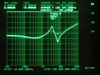
First, I started with a 470 uF / 100 nF small film cap combo, because the SMD ceramic one kept on braking on me..
The highlighted curve is the resonance peak / dip generated by the 470 uF/63 v // 100nF /63v combo.
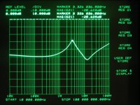
The second trace is the same, but there is a small size .22 ohm put in series with the film cap, towards ground.
As it can be seen, both the resonance peak / dip are dampened, the resulting impedance trace is smoother, but there is the obvious loss in decoupling effectiveness towards the high frequency asimptot, not only the loss at around the series resonance dip [which is a small area, as I noted before]. This loss is at around 2 - 3 dB.
Pardon me for the photo quality, the next ones will be better.
Note the resonance peak without damping, it reaches more than 1 ohm. This is the problem, which could cause ringing at switching edges.
The res. peak is at around 3 MHz.
Maybe it can be still interesting, so I would post the graphs in question..
First, I started with a 470 uF / 100 nF small film cap combo, because the SMD ceramic one kept on braking on me..
The highlighted curve is the resonance peak / dip generated by the 470 uF/63 v // 100nF /63v combo.
The second trace is the same, but there is a small size .22 ohm put in series with the film cap, towards ground.
As it can be seen, both the resonance peak / dip are dampened, the resulting impedance trace is smoother, but there is the obvious loss in decoupling effectiveness towards the high frequency asimptot, not only the loss at around the series resonance dip [which is a small area, as I noted before]. This loss is at around 2 - 3 dB.
Pardon me for the photo quality, the next ones will be better.
Note the resonance peak without damping, it reaches more than 1 ohm. This is the problem, which could cause ringing at switching edges.
The res. peak is at around 3 MHz.
Attachments
Well even if this particular idea didn't immediately bring any "advancements to the art", seeing someone look at things in this detail is refreshing. Looking forward to further brainwaves from your part!
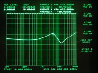
In the next step I was more succesfull in installing a 0806 / 100nF /50 V smd capacitor. So here it is the resonance generated by the 470 uF // 100 nF smd parallel combo. Though the ESR of these two caps is not very much different, because of the much lower stray inductances, the high freq. attenuation effect is better by ~ 10dB. Also the series resonance dip is shifted to a higher frequency.
Attachments
Yes, but the parallel resonance is the one that's causing trouble. The series inductance which is part of the series resonance shows up as part of parallel LC circuits formed by the Cd of the "off" fet and the inductance of the mosfet leads and to a lesser extent the decoupling cap. Here, the inductance of the cap is clearly negligible. On the other hand, the lower inductance clearly does pay off towards keeping the supply feed clean (requiring the layout to be "4-point").
Now I have put the "snubbing", small capacitor in parallel. So here there is the 470 uF // 47 uF // 100nF combo.
The resonance peak is damped, the dip is unchanged, and as a beneficial effect of the new cap's self-inductance paralleling out the original combo's ESL, the high frequency attenuation has dipped by ~ 3-4 dB. Also the resulting ESR is decreased a bit, though not much.
So, as a sum, this variation is really a much better decoupling method, then putting the series resistance.
In my defense I could only note, that as you can see, the resulting impedance / phase curve is, anyway, smoother with the series resistance method. [less ringing?] Maybe a combination of these could work? Note also that the parallel resonance peak had been damped in an equal manner, in both cases. [Though I was using only .22 ohm]
Ciao, George
Attachments
P.S.>
I just got curious about this last possible combination that I have previously mentioned:
470uF // 47 uF // 100nF smd +.22 ohm series
Well, it still shows a lot of degradation in the high frequency range - but I will also show You the practical setup, so as to be able to judge: worse than this would be really difficoult.. so what would happen if it were realized on a pcb, with - one - smd resistor?
The highlighted trace is the impedance, the second one is the phase.
You would not want to see the phase plot of the previous graphs...


Most certainly the HF performance would be better. It's not very hard to try it out in practice. One can lift the 100nF off the PCB and solder it back in series with the smd resistor in a "card-house" fashion. I don't have an EMC test rig here (it's in Groningen, about 350kms north from here), but it's something to try out. If EMI is not significantly affected, the next step is to see if we find an improvement in audio performance.Joseph K said:so what would happen if it were realized on a pcb, with - one - smd resistor?
Jumpier as Q's are higher of course.Joseph K said:You would not want to see the phase plot of the previous graphs...
Looks like a normal jig for network testing to me 🙂Joseph K said:And the jig [uugghhly..]
I was thinking of the "card-house" as well! It would be nice to hear some feedback.. Though it's just an another type of tradeoff, it's quite clear.
Ciao, George
Ciao, George
Dear Joseph: Thank you very much for the effort that you have spent in making the measurements, and the nicely detailed graphs. Looking at your test setup, however, you have what appear to be unnecessary amounts of parasitic inductance in the long leads of the 470uF electro. Trimming these to a shorter and more precise length may yield better and more consistent results (unless the lead lengths in the photos have already been tuned for the best results through trial-and-error iterative testing).
Also, in my experience, a 10:1 ratio with caps (470uF // 47 uF)doesn't always help the higher frequency impedances as effectively as I would like. I find that I tend to get better results from 50:1 or 100:1 ratios. Admittedly, however, each component and each situation is different. One of my goals is to get the most efficient results from the number of components used and the board volume that they consume.
appreciative regards, jonathan carr
Joseph K said:oops, the plot:
Hi Joseph,
Nice studies, what about using a 470uF cap with a 47 or 100uF cap that has a similar series resistance. I found that my 47-100uF 100V BG caps have a series resistance similar of normal caps that are 5-10 times larger in value, this may lower the peak at 3Mhz??? Of course the 100nF cap may still be needed as a snubber (with the series R). I tested BG caps with 100nF in parallel, this gives ringing at a few Mhz, so not desired, need to snub it away.
Best regards
Gertjan
Dear Jonathan!
Yes, that was intentional, though Bruno should correct me, if I were exaggerating. As you noticed, I could have put the big cap with almost zero lead lenght, as well. But Bruno was writing about the extra parasitic inductance of the leads, and I think in an actual design some loop area is unavoidable. While this kind of test jig setup is very - or rather too much - generous in providing an easy access to the test points, the reality is different..
Then, this test was just indicative - as you said, for simulating the real configuration, for example, of an UCD 180, one should absolutely use the same parts, as a start. I am dead sure that the ESR / ESL figures for the particular main cap in the UCD are different from those here. Though I would estimate that it would have a lower ESR value, with ESL remaining similar [dictated by the form factor & voltage tolerance], and in this way generating even more peaking.. actually a medium ESR standard cap behaves better from this particular point of view.
The small cap was chosen, again, based upon what Bruno said and for what it is supposed to serve - having a medium-highish ESR value, and serving here as a "snubber". Then, finally, I am dead sure that also the smd type 100nF cap used by me is actually more generous than in the real setup - it's a 50V type, and in the UCD it should be as a minimum 100V. This means, it has an even lower ESR, again, peaking more pronounced. Well, I am always talking about peaking, but as we have seen, all this means also that the UCD obviously have a much better high freq. attenuation, too.
Then, another point. The test points themselves. Here, as I have pointed out in an earlier thread, I have 50 ohm termination on both sides of the jig - that is, 25 ohm load on the test line. So any kind of [parallel] impedance peak is actually damped by this 25 ohm. So, in some cases we actually get a better picture, than it would be in a real setup, where the actual load maybe is less [higher than 25 ohm].
While in this particular setup, where we are looking at a power amp setup, this load seems to be quite all right, in case of small signal bypass test I usually get a much better than real picture.
On the other hand, You are right saying that this type of bypass config is not the ultimate and only one - obviously it's possible to play with other setups, as well. And, as You said, there are a lot of external points to take into account, as well. In this I trust Bruno, and their optimization process.
As regards at the 100:1 ratio - I 'm a liitle afraid of that. The further away on the bode plot you get from the first zero, the more chance you get for a more pronounced resonance/ peaking between the two parallel units.
Ciao, George
you have what appear to be unnecessary amounts of parasitic inductance in the long leads of the 470uF electro
Yes, that was intentional, though Bruno should correct me, if I were exaggerating. As you noticed, I could have put the big cap with almost zero lead lenght, as well. But Bruno was writing about the extra parasitic inductance of the leads, and I think in an actual design some loop area is unavoidable. While this kind of test jig setup is very - or rather too much - generous in providing an easy access to the test points, the reality is different..
Then, this test was just indicative - as you said, for simulating the real configuration, for example, of an UCD 180, one should absolutely use the same parts, as a start. I am dead sure that the ESR / ESL figures for the particular main cap in the UCD are different from those here. Though I would estimate that it would have a lower ESR value, with ESL remaining similar [dictated by the form factor & voltage tolerance], and in this way generating even more peaking.. actually a medium ESR standard cap behaves better from this particular point of view.
The small cap was chosen, again, based upon what Bruno said and for what it is supposed to serve - having a medium-highish ESR value, and serving here as a "snubber". Then, finally, I am dead sure that also the smd type 100nF cap used by me is actually more generous than in the real setup - it's a 50V type, and in the UCD it should be as a minimum 100V. This means, it has an even lower ESR, again, peaking more pronounced. Well, I am always talking about peaking, but as we have seen, all this means also that the UCD obviously have a much better high freq. attenuation, too.
Then, another point. The test points themselves. Here, as I have pointed out in an earlier thread, I have 50 ohm termination on both sides of the jig - that is, 25 ohm load on the test line. So any kind of [parallel] impedance peak is actually damped by this 25 ohm. So, in some cases we actually get a better picture, than it would be in a real setup, where the actual load maybe is less [higher than 25 ohm].
While in this particular setup, where we are looking at a power amp setup, this load seems to be quite all right, in case of small signal bypass test I usually get a much better than real picture.
On the other hand, You are right saying that this type of bypass config is not the ultimate and only one - obviously it's possible to play with other setups, as well. And, as You said, there are a lot of external points to take into account, as well. In this I trust Bruno, and their optimization process.
As regards at the 100:1 ratio - I 'm a liitle afraid of that. The further away on the bode plot you get from the first zero, the more chance you get for a more pronounced resonance/ peaking between the two parallel units.
Ciao, George
Gertjan,
This really is the field of Bruno. I'm sure he will have some kind words to You 🙂 - after having explained some times, that he uses this cap as a snubber..
Now, apart from joking, it's a good question. But first I would like to try to explain the "snubbing idea of Bruno, if I may? So, let's suppose we have the parallel combo of 470uF // 100nF. Let's leave out now the big cap's C, look at it only like it's ESL, and examine the LC tank formed by this ESL // 100nF. Because both the 470uF's ESR and the 100nF's ESR are equally low, the resulting parallel resonance peak is high - the resonating currents can run to and fro between the two units undamped - there is no energy loss in the circuit. Now if we tie accross a new piece of capacitor, obviously again in parallel with the original one, and it's low ESR himself, again, then You just changed the resonance frequency for lower, but did not change the energy distribution - the resonant currents continue to exchange geefully...
But if you tie across the LC tank an RC element, which presents a C acceptable low at the resonant freq, AND an R just optimal to "burn" away energy from the tank circuit - then you will be successfull to damp the resonances. This R can not be low - then it will not burn enough energy. Can not be too high, as well - then it will not see any current crossing it. This is the idea behind the so called "snubbering".
But. I have to admit, I start to have a slightly different idea what is going on, when you start to parallel electrolytic caps. So, let's take again our example. You have the 470 uF // 100nF combo. There is the ESL // 100nF parallel LC tank formed. Now we add up the new, low ESR BG. Did we add a new capacity, or rather something else?
I would say, else. I think we can - again - forget about it's C value, it's just more than needed. What left? It's ESL - ESR. So, it looks like we are not adding a new C value into that equation, but a new parallel ESL value to the original. The sum ESL will be dominated by this new, lower ESL of the smaller cap - and this will shift / lower the original resonance peak!
Where is it that I am mistaken?
Ciao, george
Joseph K said:Gertjan,
This really is the field of Bruno. I'm sure he will have some kind words to You 🙂 - after having explained some times, that he uses this cap as a snubber..
Now, apart from joking, it's a good question. But first I would like to try to explain the "snubbing idea of Bruno, if I may? So, let's suppose we have the parallel combo of 470uF // 100nF. Let's leave out now the big cap's C, look at it only like it's ESL, and examine the LC tank formed by this ESL // 100nF. Because both the 470uF's ESR and the 100nF's ESR are equally low, the resulting parallel resonance peak is high - the resonating currents can run to and fro between the two units undamped - there is no energy loss in the circuit. Now if we tie accross a new piece of capacitor, obviously again in parallel with the original one, and it's low ESR himself, again, then You just changed the resonance frequency for lower, but did not change the energy distribution - the resonant currents continue to exchange geefully...
But if you tie across the LC tank an RC element, which presents a C acceptable low at the resonant freq, AND an R just optimal to "burn" away energy from the tank circuit - then you will be successfull to damp the resonances. This R can not be low - then it will not burn enough energy. Can not be too high, as well - then it will not see any current crossing it. This is the idea behind the so called "snubbering".
But. I have to admit, I start to have a slightly different idea what is going on, when you start to parallel electrolytic caps. So, let's take again our example. You have the 470 uF // 100nF combo. There is the ESL // 100nF parallel LC tank formed. Now we add up the new, low ESR BG. Did we add a new capacity, or rather something else?
I would say, else. I think we can - again - forget about it's C value, it's just more than needed. What left? It's ESL - ESR. So, it looks like we are not adding a new C value into that equation, but a new parallel ESL value to the original. The sum ESL will be dominated by this new, lower ESL of the smaller cap - and this will shift / lower the original resonance peak!
Where is it that I am mistaken?
Ciao, george
Hi George,
Measuring is probably a faster way to find out. I always use a scope with a squarewave generator forming an RC network and measure the voltage over the C to see ringing and ESR. Putting 100nF Cs inparallel with low ESR caps always gives a clear ringing while high ESR caps give no ringing. This is my low cost netwrok analyzer 🙂
Gertjan
ghemink said:Measuring is probably a faster way to find out. I always use a scope with a squarewave generator forming an RC network and measure the voltage over the C to see ringing and ESR. Putting 100nF Cs inparallel with low ESR caps always gives a clear ringing while high ESR caps give no ringing. This is my low cost netwrok analyzer 🙂
I would also suggest using a simulator. If you feed it detailed enough models of the capacitors, this can be a quicker way to get a feel for things.
Gertjan,
and not a bad one.. 🙂
http://www.diyaudio.com/forums/showthread.php?s=&postid=557021#post557021:)
This is my low cost netwrok analyzer 🙂
and not a bad one.. 🙂
http://www.diyaudio.com/forums/showthread.php?s=&postid=557021#post557021:)
Bruno Putzeys said:
I would also suggest using a simulator. If you feed it detailed enough models of the capacitors, this can be a quicker way to get a feel for things.
Yes, I have tried that and it works, I`m using SwitchCad as it is free and has a nice user interface.
I also used that simulator with a simplified UcD model to simulate power supply pumping and switching noise on power rails.
Based on that, it looked like bridging two UcD amps and synchronizing them can reduce power supply noise quite a bit.
Best regards
Gertjan
Joseph K said:Gertjan,
and not a bad one.. 🙂
http://www.diyaudio.com/forums/showthread.php?s=&postid=557021#post557021:)
Can`t f nd anything there???
- Home
- Amplifiers
- Class D
- UCD180 questions