Unfortunately i don't think so,
For sure this is the perfect product for active XO...
If hypex want to develop some for DIYER i will be pleased
For sure this is the perfect product for active XO...
If hypex want to develop some for DIYER i will be pleased
OK, here's another issue..............
No matter what, I can't get any LF output from my biamped setup with a pair of UCD-180's.
I confirmed that:
PSU voltages were good (46V)
Filter was good, but replaced with a new one (to confirm that it was good.)
PSU caps were not blown
Rectifiers are good
Drivers themselves are not blown
There are no shorts in the wiring
No matter what, the modules will simply not amplify low frequencies- but both of them will amplify>100Hz- and do so with perfect clarity.
The woofers just quiver- and put-out very minimal sound.
The other speaker (from the stereo pair) works perfectly fine- and it's the exact same setup as the one that's not working.
I'm stumped- and I've tried everything I can think of.
C'mon guys, there's got to be something I'm overlooking.
Suggestions??
Try swapping modules with the one that is working?
Sounds like you have an unintentional highpass filter in there somehow. Are there any series coupling capacitors in the crossover that might be the wrong values? Or a connector that is close to (but not quite) making contact?
Sounds like you have an unintentional highpass filter in there somehow. Are there any series coupling capacitors in the crossover that might be the wrong values? Or a connector that is close to (but not quite) making contact?
Hey....................
The filter is a factory built one that the manufacturer guaranteed was working upon shipment. It's doing the exact same thing as the one I took out.
The sound is very-very low mixed with that PCM cell-phone sound. You know, the sound you hear coming-in over your TV when your cell is getting a call.
I swapped over to the other working module- and it works fine with only high frequencies, but falls flat with low frequencies. I have determined that whatever the problem is, it's common to both UCD's.
Going nuts!!
Re: OK, here's another issue..............
Mr. Dog,
I'm no expert, but have you tried each speaker "By Itself" with each channel of your amp? If you have worked on your speakers recently, you may have gotten the woofers wired out of phase with each other. Running both speakers would have the bass frequencies canceling, while a solitary speaker won't do that.
I've seen Pros do exactly what I've described and just go nuts trying to figure it out.
Best Regards,
TerryO
cadaverdog said:No matter what, I can't get any LF output from my biamped setup with a pair of UCD-180's.
I confirmed that:
PSU voltages were good (46V)
Filter was good, but replaced with a new one (to confirm that it was good.)
PSU caps were not blown
Rectifiers are good
Drivers themselves are not blown
There are no shorts in the wiring
No matter what, the modules will simply not amplify low frequencies- but both of them will amplify>100Hz- and do so with perfect clarity.
The woofers just quiver- and put-out very minimal sound.
The other speaker (from the stereo pair) works perfectly fine- and it's the exact same setup as the one that's not working.
I'm stumped- and I've tried everything I can think of.
C'mon guys, there's got to be something I'm overlooking.
Suggestions??
Mr. Dog,
I'm no expert, but have you tried each speaker "By Itself" with each channel of your amp? If you have worked on your speakers recently, you may have gotten the woofers wired out of phase with each other. Running both speakers would have the bass frequencies canceling, while a solitary speaker won't do that.
I've seen Pros do exactly what I've described and just go nuts trying to figure it out.
Best Regards,
TerryO
Re: OK, here-goes....................
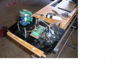
That is the Marchand XM-1 crossover boards... Very good board. I'm doing some projects with them myself.
I'm using some old XM-1 boards that I have been running in a home unit for over 15 years. Hows that for reliability!.
PS if that is a steel plate you could have skipped the massive heatsink and connected the UcD180 straight on the plate.
cadaverdog said:Steel washers used as standoffs; they tend to cause short circuits.
DUH!!
That is the Marchand XM-1 crossover boards... Very good board. I'm doing some projects with them myself.
I'm using some old XM-1 boards that I have been running in a home unit for over 15 years. Hows that for reliability!.
PS if that is a steel plate you could have skipped the massive heatsink and connected the UcD180 straight on the plate.
Yeah..............
I guess I "overengineered" that one.
The modules are internal to the speakers, so the idea is to let in air at the bottom of the plate (via the slots)- and right across the heatsink. The fan draws the air in through said slots.
I have since removed the fan- and simply covered the hole with a grate. After playing the amps for 8 hours straight at full volume, the plates never got a single degree above ambient temp.
Thanks for your reply......................
By the way.........................
Try the LM4562 in the Marchand boards, the sound is really in another league.
Highly recommended!!
Try the LM4562 in the Marchand boards, the sound is really in another league.
Highly recommended!!
I already have a couple of LM4562 SOIC version and a rather limited budget.
If I buy a couple of UCD180ST can I change the standard opamps with those?
Are there any other necessary mods to be performed on the circuit if I replace the opamps?
Do I need to add the SST511 as well?
Thanks in advance for your reply.
If I buy a couple of UCD180ST can I change the standard opamps with those?
Are there any other necessary mods to be performed on the circuit if I replace the opamps?
Do I need to add the SST511 as well?
Thanks in advance for your reply.
No, it's not necessary....more, the SST511 footprint place is not the right place for LM4562!
Thanks for your reply. Just to be sure that I understood correctly:
Yes I can replace the opamp with LM4562 without the need to modify anything else.
No, I don't need to add the SST511 and It's not advised to do so anyway.
Is that right?
Are there any other mods that it's worthwhile performing on the UCD180ST module?
Thanks
Yes I can replace the opamp with LM4562 without the need to modify anything else.
No, I don't need to add the SST511 and It's not advised to do so anyway.
Is that right?
Are there any other mods that it's worthwhile performing on the UCD180ST module?
Thanks
Member
Joined 2003
pincellone said:Are there any other mods that it's worthwhile performing on the UCD180ST module?
Probably. See the thread you're currently posting in, as well as this one.
heat sink drill hole template
I would like to suggest an improvement to the 1 page documentation that comes with the UcD180/400.
There are a couple of nice diagrams of the modules and a digram of how to wire them up but a more useful diagram would be one of the holes that are used to mount the heat sink.
If there was a cutout that could be taped onto the chassis for drilling purposes this would save DIYers, most of which are probably not metalworkers a lot of hassle.
col.
Member
Joined 2003
Do you own a ruler?
I really don't think that's necessary. The datasheet includes a mechanical drawing, showing 33mm spacing between the heatsink mounting holes. The boards are small enough that you don't even need to attach standoffs if you don't want to. The board is very mechanically stable with just being mounted by the heatsink.
Using the mechanical information in the datasheet, combined with a ruler, you should have no problems creating your own drill template, if need be. Either way, if you would like to make a suggestion, the best method of getting your ideas to Hypex would be to contact Hypex 😉.
My option was:
- mount to heatsink
- attach 2 standoffs to the board only, furthest from the heatsink.
The standoffs need not even touch the chassis; but you do have a warm feeling of added security
Andy
- mount to heatsink
- attach 2 standoffs to the board only, furthest from the heatsink.
The standoffs need not even touch the chassis; but you do have a warm feeling of added security
Andy
Hi all,
I am looking at this PSU. Just by looking at the output voltages, it fits well with the Ucd 180. Anybody has any experience with this ALP product?
http://www.abletec.com/index.php?id=34
I am looking at this PSU. Just by looking at the output voltages, it fits well with the Ucd 180. Anybody has any experience with this ALP product?
http://www.abletec.com/index.php?id=34
Wiring up UcD
Anyone know how pin 4 (On/Off) works? Does it open the input circuit, open the output circuit, open all power rail circuits, so no VDC gets to the board, open just the 12VDC circuit?
A.
Anyone know how pin 4 (On/Off) works? Does it open the input circuit, open the output circuit, open all power rail circuits, so no VDC gets to the board, open just the 12VDC circuit?
A.
Re: Wiring up UcD
It simply disables the oscillator that controls the output stage switching.
Audioch said:Anyone know how pin 4 (On/Off) works? Does it open the input circuit, open the output circuit, open all power rail circuits, so no VDC gets to the board, open just the 12VDC circuit?
A.
It simply disables the oscillator that controls the output stage switching.
- Home
- Amplifiers
- Class D
- UCD180 questions