D
Deleted member 148505
Hi All,
I am using FDP075N15A MOSFET
good for EMI
good for 1R load @ +/-68V Supply rail (Tested for 1 Hr.)
good for 2.6R load @ +/-73V Supply rail (Tested OK 10 Hr.)
good for Bridge 2.6R load @ +/-65V Supply rail (Not tested)
Tested with 1Hz freq. 4R load @ +/-55V Supply rail without heat sink 1 Hr.
Regards
MANOJ
Last edited:
words by original designer of this lovely thread topic.
Well... i was thinking if it would be worthwhile to try to answer or not to all the things that have been told about this amp. I was the designer of it, and, be sure, i know the limitations of the design. Severe compromises had to be done in order to make this design doable by common people.
Please, take into consideration that the design was severely affected by the semiconductors that are/were readily available on the local market, here in Argentina. Of course you can always buy fancy and more appropiate components from an international supplier, such as Digikey or Farnell, but that would make nearly impossible to hobbists to build it, just because it is extremely expensive and difficult to import electronic components in low quantities, at least, here.
The design lacks several features desirable for a commercial design, specially , all the required protections (short circuit, overvoltage, etc). It is also using old (but cheap and easiliy available) mosfets that are not "suitable" for class D audio. It even uses an IR211x mosfet driver, that "lacks" internal deadtime control, and requires a level shift translator (a discrete one).
And, i also agree that the board should be a double layer one with metallized holes, but, again, such board would put the design out of the possibilities of regular hobbists, because metallized holes on boards can't be done at home... And would require boards to be professionally made, rising costs again.
And , of couse, the inductor should be wound on a ferrite/metal powder core, but, again, it would mean amateur hobbists are left out of the design...
So...
Take this amp as a proof of concept, and NOT as a commercial design... It has room for lots of improvements (use more suitable mosfets, for example... add external deadtime control, redesign board as a double sided one, etc... But please, do not complain... I see none of you posting designs, all i see are people trying to get already designed and foolproof schematics that outperform, if possible, commercial designs with special components, and lots of time used to debug those designs...
Eduardo
PD: regarding the deadtime, the IR211x has non simmetric propagation delays (turn on is delayed more than turn off, so... it can be taken as internal delay... And the circuit features a basic R and diode in series with mosfet gates, to control it... So it is not fair to say no deadtime control was provided... AND i know the internal diode of this mosfet is slow... BUT, that's exactly one of the purposes of the R||D in gate network... To make the switching time a little bit slower, so we don't blow the internal diode in the process... Of course this rises the disspation of each mosfet, but allows to use slower and cheaper devices... So , lot of compromiese are here... You are free to change mosfets, if you need, so don't complain!)
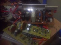
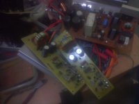
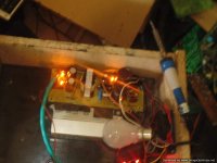
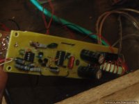
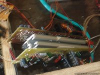
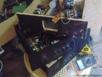
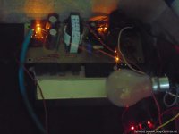
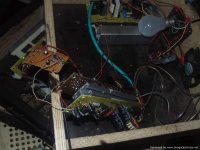
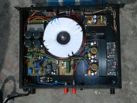
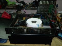
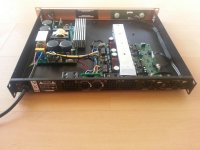
hi all my latest work and respect to the original thread so far i have tested it and is working. i will post more results and details and more clearer photos
Attachments
-
gtG ucd 1100 rev 3.1 with protect components clear v2.pdf28.9 KB · Views: 866
-
 IMG_20140612_185357_0.jpg294.7 KB · Views: 1,763
 -
 IMG_20140612_185344_0.jpg300.9 KB · Views: 1,888
 -
 IMG_20140612_185334_0.jpg296.3 KB · Views: 2,047
 -
gtG ucd 1100 rev 3.1 with protect schema.pdf31.3 KB · Views: 1,045
-
gtG ucd 1100 rev 3.1 with protect pcb v2.pdf43.5 KB · Views: 854
-
gtG ucd 1100 rev 3.1 with protect components protect full clear .pdf224.3 KB · Views: 1,123
hai enybedy help me?
iwant make a good classD amplefire but idon't have good circute
give me sombedy a circute plzzzzzzz
iwant make a good classD amplefire but idon't have good circute
give me sombedy a circute plzzzzzzz
hi all my latest work and respect to the original thread so far i have tested it and is working. i will post more results and details and more clearer photos
Hi mr Stewin
Is your pcb 2 layer or one?
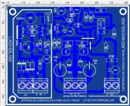
no the ucd using ir ic is single sided 🙂
wich one is beter?
your ucd amp or mr manoj aud600?
thanks
hi...
waht changes should be made to the circuit in order to use irfb4227 mosfets???
i want to power it with 2x60 volt(with smps) in order to achieve 400 watt at 4 ohm load...
waht changes should be made to the circuit in order to use irfb4227 mosfets???
i want to power it with 2x60 volt(with smps) in order to achieve 400 watt at 4 ohm load...
wich one is beter?
your ucd amp or mr manoj aud600?
thanks
manojs amp is sigma delta and this one is ucd .manojs amp is easier to mount on a casing .this one you have to mount properly to avoid switching noise .
i my self i have not been very lucky with sigma delta .if i make one channel all is o.k but if i make multiple channels in one casing using the same power supply . more than +/-55vlts one channel must fail 😱:confused (but aud 600 with protection board worked perfectly with 3 channels but when i used the 3 channels without protection board one channel failed )
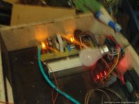
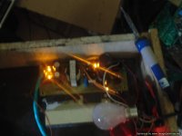
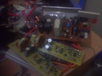
😀 so i went the ucd way .proper mounting is required but all is well at +/-63vlts at 8 ohms bridged playing really loud 😎
By the way it is working o.k without any issues but i wanted to parallel the output fets to four pairs so as to use +/-80vlts at 2ohms in bridge mode :redhot
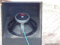
some photos of the current project i used one 18" with xocs cab design.
Attachments
-
 DSC03351.JPG122.3 KB · Views: 343
 -
 DSC03311.JPG73.3 KB · Views: 306
 -
 DSC03310.JPG53.7 KB · Views: 345
 -
 DSC03309.JPG71.4 KB · Views: 380
 -
 DSC03308.JPG61.7 KB · Views: 1,691
 -
 DSC03307.JPG93.7 KB · Views: 1,707
 -
 IMG_20140612_185357_0.jpg294.7 KB · Views: 1,822
 -
 IMG_20140612_185344_0.jpg300.9 KB · Views: 2,014
 -
 IMG_20140612_185334_0.jpg296.3 KB · Views: 2,173
 -
 DSC03334.JPG93.9 KB · Views: 422
more photos 😀😀😀
Attachments


what other transistors can i use instead of 2n5401??
i can't find them...
mpsa 92
hi andrew cool work
+/- ?? and how long have you been using your amp ? and have you ever tried to disconnect a speaker on either of the channel when the amp is playing at loud volumes??
+/- ?? and how long have you been using your amp ? and have you ever tried to disconnect a speaker on either of the channel when the amp is playing at loud volumes??

- Home
- Amplifiers
- Class D
- UCD 25 watts to 1200 watts using 2 mosfets