hi guyz about the 106-26 core i managed to add the 1mm gap with a hacksaw . my supply is +/- 70vlts the core gets hot but i've been playing it for like 7 hours .despite of the heat every thing is ok mosfets irfp260 are warm but my load is 4ohms and i'm using a very small heatsink .
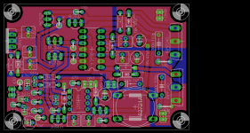
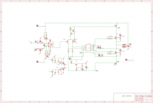
but i've noted if i increase the gap to 3mm distortion and crackling in high frequency at high volume disappears ican't explain it scientifically but it works great here are my layout and schema
but i've noted if i increase the gap to 3mm distortion and crackling in high frequency at high volume disappears ican't explain it scientifically but it works great here are my layout and schema
Attachments
hi stewin
greetings can you share pcb pattern for this amplifier failed once
want to make it again to good to miss out
thanking you
andrew lebon
greetings can you share pcb pattern for this amplifier failed once
want to make it again to good to miss out
thanking you
andrew lebon
Ok, thank you guys
Now I'm understanding this about gap and number of turns
Still, I will use core with 1mm gap and 23 turns, like all of you said, only I waiting
PCB
P.S I read somewhere about T106-26, that it has 40+10 degrees with 12 turn of 1,85mm wire (15uH) and that's totaly normal 😕😛
Now I'm understanding this about gap and number of turns
Still, I will use core with 1mm gap and 23 turns, like all of you said, only I waiting
PCB
P.S I read somewhere about T106-26, that it has 40+10 degrees with 12 turn of 1,85mm wire (15uH) and that's totaly normal 😕😛
Dzony988
Why did you make a gap in a powder toroid?
Because it was told. 🙂
To decrease flux change rate, therefore decrease heat. And to achieve higher saturation current.
Dzony988 said:P.S I read somewhere about T106-26, that it has 40+10 degrees with 12 turn of 1,85mm wire (15uH) and that's totaly normal
OK, but with what supply voltage? I guess much less than 40 V.
hi stewin
greetings can you share pcb pattern for this amplifier failed once
want to make it again to good to miss out
thanking you
andrew lebon
here is my plot but i have another which is stereo and uses droper resistor instead of transistors to power the lm311 .. pls note if you are going to use +/-70vlts change the small transistors regulating power of lm 311, from(2n5401,2n5551 ) to (bd140,bd139)respectively "remember to interchange their pins"and mount them on a small sink . not to forget also to interchange the lin and hin pins of ir2110 . "i was trying to drive the amp in an opposite phase in order to bridge it easily" 😉, never got the time to change it but i,ve managed in my another board.
thanks again andrew lebon 4 this wonderfull thread GOD bless you .
Attachments
Dzony988
because my toroid was not an iron powder one ,looks exactlly as yours but is not iron powder i have iron powder T130-2 from micrometals I bought from here
Kits And Parts Store I do not know if I'm allowed to post
I apologize if I did not
because my toroid was not an iron powder one ,looks exactlly as yours but is not iron powder i have iron powder T130-2 from micrometals I bought from here
Kits And Parts Store I do not know if I'm allowed to post
I apologize if I did not
Ok, I'm understanding my friend 🙂
What do you suggest I use, iron powder 15turns without gap (20uH) T106-26 or 23 turns with 1mm gap (17uH) t106-26
Thanks to all
Regards, Nikola
What do you suggest I use, iron powder 15turns without gap (20uH) T106-26 or 23 turns with 1mm gap (17uH) t106-26
Thanks to all
Regards, Nikola
Dzony988
because my toroid was not an iron powder one ,looks exactlly as yours but is not iron powder i have iron powder T130-2 from micrometals
😕😱
Iron powder, not iron powder, what are you talking about?
here is my plot but i have another which is stereo and uses droper resistor instead of transistors to power the lm311 .. pls note if you are going to use +/-70vlts change the small transistors regulating power of lm 311, from(2n5401,2n5551 ) to (bd140,bd139)respectively "remember to interchange their pins"and mount them on a small sink . not to forget also to interchange the lin and hin pins of ir2110 . "i was trying to drive the amp in an opposite phase in order to bridge it easily" 😉, never got the time to change it but i,ve managed in my another board.
thanks again andrew lebon 4 this wonderfull thread GOD bless you .
Hi Stewin:
Thanks for sharing the design! What is the maximum voltage can be applied and what will be output (Watt)?
Thanks
Raj
Perhaps it was a ferrite toroid, not iron powder? I am quite a fan of the white ferrite 'Polo Mint' gapped toroids from Ferroxcube, but wish that RS or Farnell or similar stocked them.
Hi Stewin:
Thanks for sharing the design! What is the maximum voltage can be applied and what will be output (Watt)?
Thanks
Raj[/QUOTE]
the voltage i,ve used is +/-70 but i replaced the regulating transistors of lm311 to bd 139&140 and mounted them on a small heatsink the outputs were irfp260 i am not sure of the wattage cause i am not a pro in calculations and i have no clue of how to use a scope . but from my ears point of view the amp is powerful and has lots of power to spare😛 stewin
Im gonna try a small modification on this circuit, tie pin 1 on LM311 to ground and use pin 7 as output instead, according to the datasheet, the LM311 would have much shorter rise and fall time with pin 7 as output.
Heres a schematic of what im gonna try:

Hello, old posting but for what is PAD 1 and PAD 2 ?
Delay ?
Hello, old posting but for what is PAD 1 and PAD 2 ?
Delay ?
That's where you connect supply for IR2110. (12-15V to negative main supply)
Im beginner for Class D and need more basic information....
cant find instruction guide for this amp
1. How much is the Dead time and how to set different DEAD TIME in this design ?
2. How to set DC Offset in this design ?
3. Is it possibile to drive 2 IRFP 250N Parallel ?
cant find instruction guide for this amp
1. How much is the Dead time and how to set different DEAD TIME in this design ?
2. How to set DC Offset in this design ?
3. Is it possibile to drive 2 IRFP 250N Parallel ?
Im beginner for Class D and need more basic information....
cant find instruction guide for this amp
1. How much is the Dead time and how to set different DEAD TIME in this design ?
2. How to set DC Offset in this design ?
3. Is it possibile to drive 2 IRFP 250N Parallel ?
1. Dead-time is approx 30 nS in this design (20 nS from IR2110 + 10 from comparator+lvelshift). You can't change dead-time, but you can change "effective dead-time" by the R + diode network to the fets. Diodes discharge fets fast, and resistors charge them slow. If you increase resistor value you increase "effective dead-time"...
2. So far I had no issue of DC offset in this design. DC offset can be lowered by lowering circuit propagation delay, this can be achieved by other connection of LM311 (see before), and even by using faster comparator.
3. To drive 2 fets per side with one IR2110, you need to increase "effective dead-time", becouse discharge current per fets is divided by two and etc. This will lead you to decrease switching frequency, the minimum should be 200 kHz (otherwise there would be no sufficient filter from LC circuit, or by desigining LC rollof to lower freq, you get huge inductors and capacitors).
To ensure proper driving multiple fets, you should use IR2010, a totem-pole for each fet after IR2110, or use Zetex integrated drive boosters (cheap), or any other equivalent solution.
But if you want HIGH POWER, you should forget IRFP250N-s, use IRFB4227 or any other FET designed for high freq switching operation (IRFB4229, IRFB4228, IRFB4332, FDP2552, FDP2532 lots of them, they worth their price). If you want even HIGHER POWER, you sould multiple these high freq switching fets. (or pray...)
thanks 4 the info .but how about driving multiple of irfp260 with small bjts like 2n5401&5551 after the ir2110 ?
1. Dead-time is approx 30 nS in this design (20 nS from IR2110 + 10 from comparator+lvelshift). You can't change dead-time, but you can change "effective dead-time" by the R + diode network to the fets. Diodes discharge fets fast, and resistors charge them slow. If you increase resistor value you increase "effective dead-time"...
2. So far I had no issue of DC offset in this design. DC offset can be lowered by lowering circuit propagation delay, this can be achieved by other connection of LM311 (see before), and even by using faster comparator.
3. To drive 2 fets per side with one IR2110, you need to increase "effective dead-time", becouse discharge current per fets is divided by two and etc. This will lead you to decrease switching frequency, the minimum should be 200 kHz (otherwise there would be no sufficient filter from LC circuit, or by desigining LC rollof to lower freq, you get huge inductors and capacitors).
To ensure proper driving multiple fets, you should use IR2010, a totem-pole for each fet after IR2110, or use Zetex integrated drive boosters (cheap), or any other equivalent solution.
But if you want HIGH POWER, you should forget IRFP250N-s, use IRFB4227 or any other FET designed for high freq switching operation (IRFB4229, IRFB4228, IRFB4332, FDP2552, FDP2532 lots of them, they worth their price). If you want even HIGHER POWER, you sould multiple these high freq switching fets. (or pray...)
Thanks for your information
1. Ok I hope i dont have missunderstood.....
This means, FETs designed for high freq switching operation like IRFB4229, IRFB4228, IRFB4332, FDP2552, FDP2532.... I can paralleling two pcs. from this fets with IR2110 but without using totem-pole or Zetex drive boosters
otherwise IRFP 250N high freq switching fets can work too but its a bad solution
2. Zetex integrated drive boosters (cheap)
I dont know this devices which is the Model Number from zetex IC ?
3. To increase "effective dead-time" for paralleling 2 pcs. IRFP 250N or IRFB4332 which resistor value would you recommend ?
4. Do you know a good working Short Circuit and overcurrent protection for this amp ?
Last edited:
Thanks for your information
1. Ok I hope i dont have missunderstood.....
This means, FETs designed for high freq switching operation like IRFB4229, IRFB4228, IRFB4332, FDP2552, FDP2532.... I can paralleling two pcs. from this fets with IR2110 but without using totem-pole or Zetex drive boosters
otherwise IRFP 250N high freq switching fets can work too but its a bad solution
2. Zetex integrated drive boosters (cheap)
I dont know this devices which is the Model Number from zetex IC ?
3. To increase "effective dead-time" for paralleling 2 pcs. IRFP 250N or IRFB4332 which resistor value would you recommend ?
4. Do you know a good working Short Circuit and overcurrent protection for this amp ?
1) Propably you can parralel two low gate charge devices since 2x70nC<234nC (2pc IRFB42227, 1 pc IRFP260N), if you don't need full-audio-spectra ergo high switching spped. But one IRFB4227 worth about 2pc of IRFP260N, and about 4pc of IRFP250N (with about 1/10th of switching losses!)
2) they start with ZXGD300, lots of them, here they cost about half euro.
3) It depends even on you layout, so I can't give exact values. But you should calculate the time to charge a fet to its on threshold voltage, and to discharge a fet to it, then calculate some safety time, then the normal dead-time... It's complicated, the best is experiment: start the circuit with some power resistors (i use 47r 5W) in the main supply lines... It will protect the amp. If everything is ok, they should be cold, when the amp is operating. If they are hot, you should recalculate you values...
4) I haven't tried any of them yet. The IR application notes recommends checking fet on-voltages after the torn on (+short delay), this what they use in IRS2092, of course you can go that way. Or you can use a shunt (boring) and measure the voltage on it, like on Tripath modules. A protection circuit should connect SD pin to high value, then IR2110 stops.
First you should build a small power one. Two IRFB4227 can get really high power, with extremely low losses. So think about parraleling them later! With my second prototype I turned my dummy-load to water-boiler and out the water I made them glow red. (I measured 200W before clipping to 8 Ohm, from 2x63V supplies, but I'm sure it can go much higher) And the FETs with their small sink even could go to an OldSp*ce advertisement.
Hello guys,...please check this schematic
have found this Turn on Delay fast off - over current and short circuit protection with two ICs NE555 and LM311 in professional Class D amp and add
could this work with our UCD ?
R48 is current sense resistor
but R42 with 270E = 270R ? ....is this ok
Other good things are DC Fault protection and Input Limiter
waiting for feedback and comments .....
Attachments
- Home
- Amplifiers
- Class D
- UCD 25 watts to 1200 watts using 2 mosfets