hi manojtm whether there was any wrong or is there something else?😀Hi,
Good PCB,Only single mistake 😉
Regards
MANOJ
Hi,
Good PCB,Only single mistake 😉
Regards
MANOJ
wow ! thank you I'm happy that was just one last minor mistake I will fix and post later sir 🙂 I'm really happy ! thank for helping me if some one want black and white PDF let me know I will post here

ok here we go cap fixed
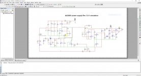
I'm also re-drawing the AUD600 supply is not completed yet
Best Regards
Juan
http://www.diyaudio.com//www.pinterest.com/pin/create/extension/
Attachments
Last edited:
hi manojtm whether there was any wrong or is there something else?😀
hi sir is not the first time I'm doing this 🙂 but as humans there's always something that escape our eyes 😉
Regards
Juan
http://www.diyaudio.com//www.pinterest.com/pin/create/extension/
Attachments
Last edited:
Hi Juan,
Power AUD600, Don't need 2K/5W & Z12V.DC protect(relay) work on same Bias Supply, and you are not provided AC fail ckt. see rev.3.0.1 schema, also see Relay contact points(C,NC & NO) on ckt.It is very important for avoid relay contact failure.
Regards
MANOJ
Power AUD600, Don't need 2K/5W & Z12V.DC protect(relay) work on same Bias Supply, and you are not provided AC fail ckt. see rev.3.0.1 schema, also see Relay contact points(C,NC & NO) on ckt.It is very important for avoid relay contact failure.
Regards
MANOJ
Last edited:
Hi Juan,
Power AUD600, Don't need 2K/5W & Z12V.DC protect(relay) work on same Bias Supply, and you are not provided AC fail ckt. see rev.3.0.1 schema, also see Relay contact points(C,NC & NO) on ckt.
Regards
MANOJ
I just begin the other day sir the PCB is going to be changed some components, that is why I say is not completed 🙂 I will fallow the rev 3.0.1 schema, and yes I notice that 2K/5W is not needed 😉 I will post later in a few day I have to "brainstorm a lot now" 😀
Regards
Juan
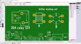
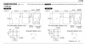
hello manoj can you give a example of a bifilar winding ? I made two macros one to flat surface and one upright mounting also, I read on schematic that relay need to have a 30A contract type is this relay type will be ok to use ?
Regards
Juan
Regards
Juan
Attachments
Hi All, few years ago I made UCD, but I changed feedback network a little.
Are there any feedback network changes here? To improve THD rating even better.
Also I would like that someone write down subjective "hearing" opinion, comparing class AB (high quality AB class amplifier) with UCD, using same speakers, same "music".
Are there any feedback network changes here? To improve THD rating even better.
Also I would like that someone write down subjective "hearing" opinion, comparing class AB (high quality AB class amplifier) with UCD, using same speakers, same "music".
Hello gentlemen
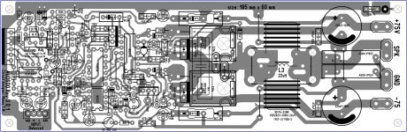
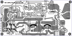
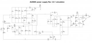
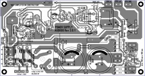
I spend a couple of hours yesterday on the AUD600 power supply board and I made a few changes the capacitor now larger ones can be use up to 35 mm in diameter at the moment of this writing, also I decide to change the bridge rectifier to one that can handle more current up to 600V 50A "actually I'm fallowing mister manoj schematic", part number MP506W-BP I change the relay to a one that can withstand more current on the contacts 30A part number JTN1AS-PA-F-DC12V.
mister manoj let me know if this relay I can used for the circuit
I still working on it this and it still a draft not a completed PCB yet but I will post a couple of time as I go good day guys 🙂
Best Regards
Juanhttp://www.diyaudio.com//www.pinterest.com/pin/create/extension/
Attachments
Last edited:
Hi,
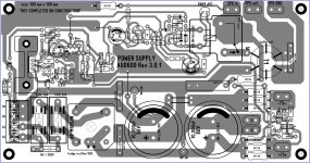
This BR diode🙂 I used for AUD1000SD(smd version)
Regards
MANOJ
nice sir, even better ! 🙂 I think I will changed for that one thanks,
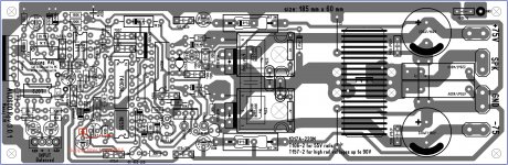
this is how it look now but I do not mind changed to that part number 😀
(the image you see here might have errors I still checking) just in case jejejejejeje 😛
Regards
Juan
http://www.diyaudio.com//www.pinterest.com/pin/create/extension/
Attachments
Last edited:
can anybody help, i need class D schematic include balance input, resonant reducer and dc protect. and use for supply 120vdc ct. Thank's
Hi Juan,
Nice work.Your PCB size is little big (190x100 mm).
You can add HOPS and UV/OV ckt on this PCB(Full protection)
Regards
MANOJ
Nice work.Your PCB size is little big (190x100 mm).
You can add HOPS and UV/OV ckt on this PCB(Full protection)
Regards
MANOJ
Hi Juan,
Nice work.Your PCB size is little big (190x100 mm).
You can add HOPS and UV/OV ckt on this PCB(Full protection)
Regards
MANOJ
thank you 🙂 and yes it is way too big I will try to reduce if I can🙂 yesterday I was simulated the circuit protection and respond really well to dc detect amp failing and transformer activation "if transformer is off it will shot down" or make relay off but I notice relay activate way too fast or maybe is the software that is doing that ? is there a component value that can be change to slow down the relay delay time delay activation ? maybe 10 seconds perhaps ?
Best Regards
Juanhttp://www.diyaudio.com//www.pinterest.com/pin/create/extension/
Attachments
Last edited:
Hi Juan,
Practically its @3sec delay🙂
Regards
MANOJ
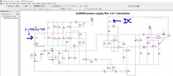
hello sir actually works really well on the simulation I forgot to add a S1 to a transformer winding to simulated transformer activity and does activate relay after 3 sec 🙂 also DC detect work good too 😀
I forgot to ask, what voltage I need to read on pin one bias ?
Regards
Juan
http://www.diyaudio.com//www.pinterest.com/pin/create/extension/
Attachments
Last edited:
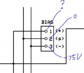
I most have done something wrong, 😕 on pin one bias I have -63V and pin 3 (-) is -75V
I found the info in post #3134
so pin one need to be +12 right ? 🙂 maybe is better if I use a separate 12V regulator and add a small bridged rectifier for the 12V IC regulator to use a separate small transformer or from the same toroid
Regards
Juanhttp://www.diyaudio.com//www.pinterest.com/pin/create/extension/
Attachments
Last edited:
I most have done something wrong, on pin one bias I have -63V and pin 3 (-) is -75V
Hi Juan,
Yes the voltage what you get is correct if you measured with respect to GND { 75-12=63}
BIAS PIN 1 is +12V with respect to -HV Supply rail (BIAS PIN 3)
Regards
MANOJ
Last edited:
Hi Juan,
Yes the voltage what you get is correct if you measured with respect to GND
BIAS PIN 1 is +12V with respect to -HV Supply rail (BIAS PIN 3)
Regards
MANOJ
oh wow ! so is good to go nice ... 😀 I do have approximately 11.7V 🙂 nice so I can continue then the PCB layout at least I know DC detect and 3 sec delay is working good too

Best Regards
Juan
Attachments
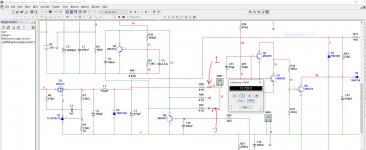
Hello mister manoj I have a little problem, the LED does not light up at any circumstance on the simulation ? what could be the reason ?
all the circuit responds really well I have 12V on pin 1 (+) and DC detect works well if detect 4V it will release the relay NC and also the transformer detection also works too 🙂
but not the LED ? 😕
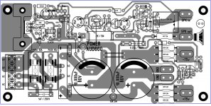
here how the layout looks now today I know is too big but maybe with time I will reduce size is possible as I go day by day
Regards
Juanhttp://www.diyaudio.com//www.pinterest.com/pin/create/extension/
all the circuit responds really well I have 12V on pin 1 (+) and DC detect works well if detect 4V it will release the relay NC and also the transformer detection also works too 🙂
but not the LED ? 😕
here how the layout looks now today I know is too big but maybe with time I will reduce size is possible as I go day by day
Regards
Juanhttp://www.diyaudio.com//www.pinterest.com/pin/create/extension/
Attachments
Last edited:
- Home
- Amplifiers
- Class D
- UCD 25 watts to 1200 watts using 2 mosfets