Hello,
Recently I was able to purchase some NOS tubes and came across 9 NOS type 50 tubes. I would like to build a type 50 tube amp.
I am not the most technical but I have a friend who is retired and an very good tech, he has agreed to assist me with the build. I have a lot of gear here, but nothing I have built myself. My reference setup includes Shindo separates and I have a few choices for speakers (most are high efficiency).
I came across this circuit and was wondering everyone's thoughts? http://roadtonirvana.net/diy/AK-300schema.pdf
I was thinking to possibly change out the Hammond output transformers for Lundahl (they make something that will work $$$). Anyway, thoughts on the above circuit? Anyone have any other the 50 tube SET circuits to consider?
THANKS
If you use a 1:2 input transformer, you could use a 5687. It would help keep the amp nice and quiet and the 5687 has plenty of current capability to drive any sort of capacitance it will run into.
The 50 was a high on the list output triode 15 or so years ago before its vendor price went from $50 to $250 in one jump.
Not everybody loved it but you'll find a quote on the Asylum from somebody saying it was what the 300B wanted to be. Anyway, you're lucky to have them.
Here's a link to a search on the SET Asylum. There'll also be more on the Tube DIY Asylum and Tubes Asylum. You can also try Tim Reese if he's still checking that email address. Ask if you can get a file of the Joelist stuff. There's probably more there.
Personally, I'd run it somewhere just above specified mid-level (Vp = 400VDC @ Ip = 55mA ) and higher than specified load impedance if you don't need the power. If you're going to go with 5K as in the Hammond , (again purely personal opinion), I'd go with the Transcendar 5K transformer instead.
A lot of people have used the 5842/417A but I get the sense that it's not the final destination for most who try them. The few times I used them they performed well electronically but I didn't get a sound result I wanted to listen to much once I'd put the tools away.
Thanks. Lots of reading...I will read them all.
I have NO plans to use the Hammond output transformer. I was thinking Lundahl
I have NO plans to use the Hammond output transformer. I was thinking Lundahl
Lundahl LL1623/60mA will do fine. It's 5.7K into 8R and becomes 4.3K if the loudspeaker load falls to 6R. Quite typical. 4.3K is the suggested load for 450V/55mA in the datasheet for 4.6W output. Into 8R power will be 4W.
The 50 should have about 30 pF miller capacitance. With 1:2 will become 120 pF as seen by the driver. The main issue however is that all 1:2 interstage transformers have poor bandwidth in comparison to what can be done with 1:1.
I am more for a triode connected D3a or similar with a 1:1 bifilar interstage like Monolith Magnetics IT01/25 mA or if going for a 3 stages integrated amp one can also use the Sowter 9525 with a 2A3.
Sowter type 9525
If you use a 1:2 input transformer, you could use a 5687. It would help keep the amp nice and quiet and the 5687 has plenty of current capability to drive any sort of capacitance it will run into.
The 50 should have about 30 pF miller capacitance. With 1:2 will become 120 pF as seen by the driver. The main issue however is that all 1:2 interstage transformers have poor bandwidth in comparison to what can be done with 1:1.
I am more for a triode connected D3a or similar with a 1:1 bifilar interstage like Monolith Magnetics IT01/25 mA or if going for a 3 stages integrated amp one can also use the Sowter 9525 with a 2A3.
Sowter type 9525
I was talking about an input transformer not an interstage transformer.
To be honest, I am more or less in the same situation as the OP and I don't quite like the headaches of the 417a. I actually have some 417as in my dac and they make me pull my hair out.
As an alternative I was looking at the sowter transformer volume control. They have a skew where the last step is a +3db (1:2) step up. So you can handle your volume control and gain issues all in one nice neat little package.
50's were built for transformer coupling. The max grid resistance is 10K, which is why a lot of people avoid them. OTOH they don't need a lot of drive and they are amazingly even and transparent in presentation. Your option would be an interstage transformer, a choke on the grid like the one in the schematic, or a direct-coupled cathode-follower driver.
Your option would be an interstage transformer, a choke on the grid like the one in the schematic, or a direct-coupled cathode-follower driver.
Yes, a voltage follower DC coupled to the #50 grid, but use a MOSFET, not a triode, for that duty. Members George Anderson (tubelab) and Pete Millett have beaten the path.
The advantages of the FET include no heater power consumption and no worries about heater to cathode voltage limits. FWIW, a number of members think that FETs sound better, in this role.
I was talking about an input transformer not an interstage transformer.
The reason for the interstage is that with the 50 was highly recommended the use of max 10K grid resistor or transformer coupling that can be done without any grid resistor. It has a precise sense.
With a step-up you are going to load the preamp limiting your options quite a lot.
I have no experience with a 50 but I have plenty of experience with the 417a as a driver. I use a 417a with IT coupling to a 46, and it sounds great. I have never had any oscillation problems despite Eli D’s oft-stated warnings. However, you absolutely must use a grid stopper resistor, something missing from your schematic. I use a 1K Riken carbon film on one of the grid connections and I clipped off the tube pins for the other two grid connections. As I said, no oscillation issues at all. In my case I have two Red LEDs in the cathode, and I use an OD3 to supply the IT with 150v. Very simple, and it sounds excellent.
The reason for the interstage is that with the 50 was highly recommended the use of max 10K grid resistor or transformer coupling that can be done without any grid resistor. It has a precise sense.
With a step-up you are going to load the preamp limiting your options quite a lot.
Ah ha, I see. That seems kind of weird. I wonder why the grid resistor value is so low.
I'm still around, at the same address. JC Morrision published this design using the 50 in 1994's Sound Practices. He has some discussion of the grid swing required for the 50, and uses a 6SN7 cathode follower in a manner similar to the previous discussion using a FET. I recall someone is selling reprints of this Journal somewhere on the net, if you are interested.
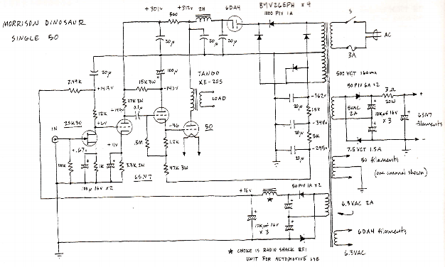
The article claims that 50s were all gone in 1994 (!) and the reader should not try to find some. It then gives some suggestions for using this circuit with 300Bs or Chinese 845s.
The article claims that 50s were all gone in 1994 (!) and the reader should not try to find some. It then gives some suggestions for using this circuit with 300Bs or Chinese 845s.
Last edited:
Ah ha, I see. That seems kind of weird. I wonder why the grid resistor value is so low.
I've always thought that it was because the spec was developed when tube technology was still fairly young and making tubes with a real hard vacuum was more difficult.
I suspect that this is a limit you could violate with later production type 50 tubes, but I'd be very careful with such valuable tubes.
I once scored a Cunningham globe 50 with engraved base for $5 at a local antique shop. It's up on display in the living room. Beautiful tube.
Last edited:
Ah ha, I see. That seems kind of weird. I wonder why the grid resistor value is so low.
Highly undesirable grid leak biasing effects set in quickly with the #50 and the tube runs away.
 As previously indicated, lack of vacuum "hardness" is a potential cause. The #50 datasheet clearly provides biasing warnings.
What has me thinking that something in addition to a "soft" vacuum contributes to the low limit is an examination of the #45 datasheet. The #45 is much more forgiving and it's (IMO) likely the vacuum in that type is no "harder" than that found in the #50.
A grid stopper resistor connected right at the 417 socket tab should prevent oscillation of the 417.
The 417 can be microphonic.
As Eli said earlier, you could use a 6C45pi, but with similar considerations as above.
What is the distributed capacitance of the 5000H grid coil?
The plate impedance of the 417 has to drive that capacitance.
The capacitive reactance of the grid coil:
Xc = 1/(2 x pi x f x c).
Now set Xc = the 417 rp, and solve for f.
At the frequency, f, where 417's rp = Xc; that f is the -3dB point.
At f x 1/2, that is the -1dB point.
Last edited:
I think the warnings about the max value of the grid resistor apply to (or are at least recommendable for) the older globe 45 too in the same fashion as the 50. Possibly to early 45 ST types (with engraved base). The latter 45 ST with printed base does not have any problem and the same rule of thumb as other tubes can be followed (i.e. max 500K if fixed bias, max 1M with cathode bias).
Possibly the type 50 in ST16 (smaller) glass is the same as the 45 ST printed base.
Anyway transformer coupling with no grid resistor is the best choice IF the interstage is high quality, IMHO.
This is not the kind of tube where max anode efficiency is of primary concern. A tube with 2 mA/V gm will never be very efficient and driving into positive grid field will shorten its life. Something one should not consider when looking at how scarce this tube has become. If one wants more power a better solution is a 300B.....
So I’m still conflicted and looking for more circuit ideas.
I was reading Sound Practices and they have a circuit from Electra Print using of course Electra Print transformers. It looks quite simple.
I will see if I can scan it or find it somewhere to add to the thread.
I am concerned about tube life. While I have (9) tubes, I would prefer to not kill the tubes extremely quick if possible...
If anyone knows of the Electra Print or can post it, please do.
It is from SP Vol 2:3 issue 7
It uses:
6AQ8
12HG7
300B or 50
- Status
- Not open for further replies.
- Home
- Amplifiers
- Tubes / Valves
- Type 50 Tube Amp