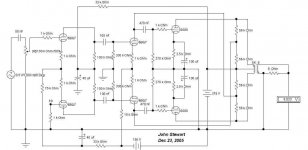
Here's Jack's amp:
The grid resistance here would concern me. If I understand this, it's about 5x what the data sheet says is the maximum for the 50.
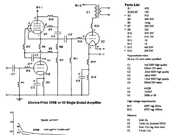
JC's amp is in Vol 2, #1 if you have that. I think it looks complicated because he makes a lot of different voltages in the power supply, and had to use some not-obvious configurations to get the voltages he wanted. Otherwise it's pretty simple, and only 2.5 tubes per channel - the 50, a 6SN7 and the damper diode 6DA4 for both channels. The damper diode just controls the warmup, and has no other function. I'd point out that he used a high-priced output transformer (expensive even then) that I expect this tube is worthy of. Jack's iron is excellent too, but he makes a lot of the distortion cancellation of this selection of tubes. This article makes an example of the 300B, and I wonder if that would work out the same with the 50.
The grid resistance here would concern me. If I understand this, it's about 5x what the data sheet says is the maximum for the 50.
JC's amp is in Vol 2, #1 if you have that. I think it looks complicated because he makes a lot of different voltages in the power supply, and had to use some not-obvious configurations to get the voltages he wanted. Otherwise it's pretty simple, and only 2.5 tubes per channel - the 50, a 6SN7 and the damper diode 6DA4 for both channels. The damper diode just controls the warmup, and has no other function. I'd point out that he used a high-priced output transformer (expensive even then) that I expect this tube is worthy of. Jack's iron is excellent too, but he makes a lot of the distortion cancellation of this selection of tubes. This article makes an example of the 300B, and I wonder if that would work out the same with the 50.
Last edited:
Another possibility - Tubelab Single Ended: http://www.tubelab.com/images/AssemblyManualTubelabSE/TSE_board.jpg There will be a new version of this board any day now that could support the 7.5V filament needed for the 50. A safe option for your valuable tubes, I'd think. There's a Tubelab forum - you could post there and ask.
Being that the 50 requires a very low value grid leak resistor (</= 10k ohms), would DC coupling the driver stage plate (or cathode follower cathode) to the 50 grid be problematic?
--
--
Being that the 50 requires a very low value grid leak resistor (</= 10k ohms), would DC coupling the driver stage plate (or cathode follower cathode) to the 50 grid be problematic?--
See schematic in post #15.
Type 50 tubes do have a max of 10K grid resistor or a grid choke can be used which is smaller and cheaper .
The heaters require 7.5 volts AC or DC, only DC will work practically for HiFi Audio applications , which means a decent Constant Current Source Supply from Tent Labs , Rod Coleman and PM Millet also sells PCB kits for this application but all would require a separate AC supply of 10v 2.5A as a starting point, Hammond Part # below 10v 4A
[SIZE=+1]266L20[/SIZE]
EML 50 tube notes Note 4) The historical 50 tube was specified with max 10k grid resistor. This is a very low, inconvenient value. The high grid quality of the EML tubes, allows for the much higher values, which you find under "maximum specifications". For downward compatibility, meaning the option to use historical 50 as well, you are advised to use a maximum 10k resistor. Alternatively the Lundahl LL1670 grid choke can be used, instead of a grid resistor. This ensures downward compatibility as well, and with a grid choke, you don't need a grid resistor.
https://frank.pocnet.net/sheets/049/5/50.pdf
https://frank.pocnet.net/sheets/029/5/50.pdf
https://frank.pocnet.net/sheets/121/5/50.pdf
https://frank.pocnet.net/sheets/121/5/50.pdf
The heaters require 7.5 volts AC or DC, only DC will work practically for HiFi Audio applications , which means a decent Constant Current Source Supply from Tent Labs , Rod Coleman and PM Millet also sells PCB kits for this application but all would require a separate AC supply of 10v 2.5A as a starting point, Hammond Part # below 10v 4A
[SIZE=+1]266L20[/SIZE]
40
20V @ 2A
10V @ 4A
EML 50 tube notes Note 4) The historical 50 tube was specified with max 10k grid resistor. This is a very low, inconvenient value. The high grid quality of the EML tubes, allows for the much higher values, which you find under "maximum specifications". For downward compatibility, meaning the option to use historical 50 as well, you are advised to use a maximum 10k resistor. Alternatively the Lundahl LL1670 grid choke can be used, instead of a grid resistor. This ensures downward compatibility as well, and with a grid choke, you don't need a grid resistor.
https://frank.pocnet.net/sheets/049/5/50.pdf
https://frank.pocnet.net/sheets/029/5/50.pdf
https://frank.pocnet.net/sheets/121/5/50.pdf
https://frank.pocnet.net/sheets/121/5/50.pdf
Our Japanese brethren love these tubes, but its hard to search for 50 triode/dht/set
Here is one I know about
SG-50 - ???? - ???????????? - Yahoo!???
regards
james
Here is one I know about
SG-50 - ???? - ???????????? - Yahoo!???
regards
james
Attachments

Being that the 50 requires a very low value grid leak resistor (</= 10k ohms), would DC coupling the driver stage plate (or cathode follower cathode) to the 50 grid be problematic?
--
No, that would not be a problem. You could build a Loftin-White style SE 50 amp. Probably talking about a 600VDC power supply.
What's the point of going cheaper with the type 50?Type 50 tubes do have a max of 10K grid resistor or a grid choke can be used which is smaller and cheaper .
In the worst case, as he has got 9 tubes he could select 3 pairs and sell 3 tubes and make money to buy interstage and output transformers of high quality...
and another
The Softone IT at $120 is quite affordable and very good performance overall. It's just a bit limited at the low end because of its inductance but if the 50 is not used at full specs it can swing the full undistorted voltage down to about 35 Hz. Not a problem if the amp can only output the max undistorted power down to 35Hz. Will do fine in 99% of cases.....
The max headroom at low frequency with the RC-20 is achieved with 20 mA anode current as the product LxIa is max. In that schematics looks like the anode current of the driver is about 13 mA. For this sort of current L is around 25-27H. But there is some fbk to help too...

Being that the 50 requires a very low value grid leak resistor (</= 10k ohms), would DC coupling the driver stage plate (or cathode follower cathode) to the 50 grid be problematic?--
See schematic in post #15.
Yes, I know. I'm asking if the theoretically near infinite grid-to-cathode resistance brought about by DC coupling would be a problem, or if I am not understanding that correctly.
My quite limited understanding is that DC coupling creates the equivalent of a near infinite input impedance at the grid of the output (driven) tube. That's normally a very good thing (blocking is nearly impossible because freq response goes down to DC), but how does this impact a tube like a 50 (or possibly a very early production globe 45) that must have a low value of grid leak setting a low input impedance at the output tube?
--
Last edited:
There are some direct coupled circuits that do not use any resistor from the output tube to ground, but these are typically only seen where the grid itself constantly draws current because it is always positive with respect to the cathode. There was a popular circuit seen about 10 to 15 years ago with a 6V6 or 6L6 directly driving the grid of an 811A. These will not work with the type 50. There must be a path for cathode current to flow in the follower, usually a resistor, choke or CCS to the negative supply.
There are some "stacked" circuits like the Free Lunch, Monkey and Loftin White, but I have never tested them.
Most directly coupled cathode or source followers use a resistor from the grid of the output tube to the negative supply. It can be a rather low value with a mosfet or some tubes.
There were at least two TSE's made with type 50's back when these tubes were still commonly available. The original TSE could not support the 7.5 volt heater, so an external supply was used. The new TSE-II will handle higher filament voltages, but it will not be ready for several more weeks, and has not been tested directly with 50's since I don't have any.
The audio path for the TSE and the TSE-II are identical. The filament supply has been redesigned due the the old version's regulator chip going extinct.
There is a resistor from the grid of the output tube do the negative supply which is fed by a mosfet source follower. A 10K resistor would not be an issue, but the standard build for 45's, 2A3's and 300B's uses 20K.
There are some "stacked" circuits like the Free Lunch, Monkey and Loftin White, but I have never tested them.
Most directly coupled cathode or source followers use a resistor from the grid of the output tube to the negative supply. It can be a rather low value with a mosfet or some tubes.
Another possibility - Tubelab Single Ended
There were at least two TSE's made with type 50's back when these tubes were still commonly available. The original TSE could not support the 7.5 volt heater, so an external supply was used. The new TSE-II will handle higher filament voltages, but it will not be ready for several more weeks, and has not been tested directly with 50's since I don't have any.
The audio path for the TSE and the TSE-II are identical. The filament supply has been redesigned due the the old version's regulator chip going extinct.
There is a resistor from the grid of the output tube do the negative supply which is fed by a mosfet source follower. A 10K resistor would not be an issue, but the standard build for 45's, 2A3's and 300B's uses 20K.
...if I am not understanding that correctly.
I'm not sure I understand what you are not understanding?
"DC coupling" *usually* means the power tube grid connects to the driver which connects to circuit commons which connect to power tube cathode.
In Morrison's plan, there is a clear DC path from the '50's grid through the 6SN7's 47k cathode resistor, to a semi-fixed voltage source B-, which returns to the '50's cathode.
Yes, this is >47k. (one way; there is also a path through the plate and B+ back to common and '50 cathode.) I am also not sure how he arrived at that: I had to fiddle values considerably to get even close to the desired bias on the '50. Also while it looks like a Cathode Follower (and is, for AC), for DC it "follows itself" (biased from its own grid) and does not have the DC stability it would have if the grid were driven with a conventional adjustable 'fixed' bias.
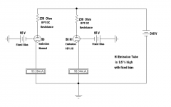
Let's think what that "10k Max" number means. A type '50 will bias with (roughly) 50V. If this bias changes +/-10%, we could be in trouble. 10% of 50V is 5V. 5V in the rated 10K is 0.5mA. The spec implies that we could have 0.5mA, direction unknown, coming through the '50's grid. This is 5 to 100 times more grid current than we expect on newer power tubes, and they allow 5 to 100 times more grid resistance.
So we set up a similar driver tube, fiddle it to a nice round -50V at cathode. Then set up a current source like it was a grid, and sweep it from -0.5mA to +0.5mA. This covers all the cases we are expected to handle at a type '50's grid.
The simulation shows the no-grid-current voltage changes +/-9.3V for +/-0.5mA. This works out to 18.7k effective driver DC resistance. While not quite the spec sheet demand, it is far from "near-infinite" as suggested.
Clearly the same driver with normal grid resistor to an adjustable -50-70V bias supply, as often seen, would show less than 1K (1/Gm) to the '50's grid.
Attachments
Last edited:
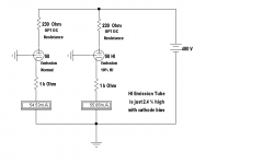
Here is another "DC coupled driver" plan we sometimes see. Plain cathode follower with a bias voltage to the grid. Now we have less than 1V of shift at the grid of the '50 when +/-0.5mA flows through the '50's grid. This is less than 1K. The '50's grid could leak 10X worse than its poor spec and still get a happy voltage. (Of course if grid current is out of control, the tube is probably very sick, but at least the grid is sitting where we put it.)
Attachments

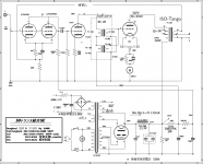
Anyone take a hard look at the AK 300 Schema? The rectifier 5AR4 with the pair of silicon diodes forms a full bridge. 700V B+ results, not good for 50s or 300Bs!🙂 Probably an error left from a previous schema. Or I missed someones comment.
Attached is a scan of the 50 characteristics from the 1933 Cunningham Radio Tube Manual; And an app note with some interesting info.🙂
Attached is a scan of the 50 characteristics from the 1933 Cunningham Radio Tube Manual; And an app note with some interesting info.🙂
Attachments
The AK-300schema.pdf has a grid choke of 5000 Henries.
A 300B has 15pF from grid to plate, a u of 3.85, and if the gain is 3.0 in circuit, there is 45pF of miller capacitance. The 5000 Henry choke will have some distributed capacitance. Even if it is Super low (say 15pF) that makes the RC resonance at 11,470 Hz.
But the distributed capacitance of the 5000 Henry choke might be 1000pF. The resonance will be in the middle of the audio band. The only thing that will solve the resonance is the swamping factor of the 417 rp that is quite low. In reality, just be sure the input stage can drive the distributed capacitance.
Just something to think about.
...5AR4 with the pair of silicon diodes forms a full bridge. 700V B+ results....
No. 350VAC end-to-end, FWB, is 350V*1.414 or 495V DC. The hollow rectifier will sag. We can in fact just use standard 5AR4 data, then subtract 1V for FR107 loss. It looks like 425V, say 424V.
There will be some drop in the choke and OT. There's numbers on the amp plan.
The cathode (filament) is up at 54V-62V.
The '50 seems to get 336V, the 300B gets 324V. Does not seem excessive. In fact the 300B seems to be run cold.
Attachments
I really screwed up on that power supply.😱 Looked to quick, I thought it was meant to be a 300-0-300 PT. It wasn't. For capacitor input filters I’ve used the simple relation that the product of 2*PI*f*Rl*C should be in the range 10 to 20. That usually results in DC volts of about 1.25X the rms of the supply. It also keeps the rms currents under control, it is the rms current that heats the PT, not the average current. The full bridge is also a plus, the utilization factor is better than with a CT AC HV. Better still UF is a result of choke input filter.🙂
For the 50 version of the AK300 circuit the Rl is 390V loaded with 51 mA, 7.65K. 10 mA to the driver 5842 is shewn on the schema. The other 41 mA appears in the paralleled cathode resistance of 2.2Kll3.3 K, 1.32K with 54V bias applied. Plugging the numbers in for a 60 Hz supply we get
~377*7.65*10^3*10*10^-6
28.82 on the HP67, a good place to be.
For stereo, multiply by 0.5, two channel load.
For 50 Hz multiply by 5/6.
Lo Mu Triodes tend to be unstable when run on fixed bias. For any power SET I would definitely run cathode bias for safety. Refer to the attachments shewing the results of comparisons of cathode current for 50s, running cathode bias vs fixed bias, when one of the 50s runs cathode current 10% above spec. Cathode bias helps quite a bit to stabilize the operating point.
Attachments
Some Add Ons
More 50s circuit info, lifted from Joe Roberts Sound Practices magazine.
Alan Douglas doesn't think much of the 50. Alan was a cornucopia of vacuum tube & tester info.🙂 Wish he had published his data on tube intro dates. For those with tube testers his book on that must be very helpful.
In the example cct of the Alan Douglas piece, cathode bias is used, a 0.75K resistor but common to both tubes.
Attachments
Two more Bootstrapped Examples
Neither of these need the UL tapped OPT I'd used in the original amp. Using a voltage divider across the OPT primary of about 50% on each side, also calculated to give proper loading to the driver tube.
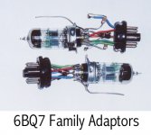
An early vers uses a pair of 6BQ7 as diff amps. This one is simulated only, I didn't do the breadboard. But I'd already made adapters to try tubes like the 6BQ7 as an alternative to the rather expensive 6SL7 & 6SN7 normally used. Tests of IMD & THD shewed the 6BQ7 to be very close in performance to what I had used on the Crowhurst Twin Coupled Amp project. In a double blind test its unlikely anyone with normal hearing would be able to hear the difference.
Recently I tried a bootstrapped 6SL7 driving the 5998. Worked OK, I left it at that. Depending on the supply the 5998 in PP clips at about 10 watts. The OPT was a Hammond 125E. No need for botique parts!🙂
Neither of these need the UL tapped OPT I'd used in the original amp. Using a voltage divider across the OPT primary of about 50% on each side, also calculated to give proper loading to the driver tube.
An early vers uses a pair of 6BQ7 as diff amps. This one is simulated only, I didn't do the breadboard. But I'd already made adapters to try tubes like the 6BQ7 as an alternative to the rather expensive 6SL7 & 6SN7 normally used. Tests of IMD & THD shewed the 6BQ7 to be very close in performance to what I had used on the Crowhurst Twin Coupled Amp project. In a double blind test its unlikely anyone with normal hearing would be able to hear the difference.
Recently I tried a bootstrapped 6SL7 driving the 5998. Worked OK, I left it at that. Depending on the supply the 5998 in PP clips at about 10 watts. The OPT was a Hammond 125E. No need for botique parts!🙂
Attachments

- Status
- Not open for further replies.
- Home
- Amplifiers
- Tubes / Valves
- Type 50 Tube Amp