Hi,
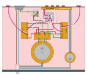
building a 3875 amp with a source selector and pot in same chassis,
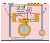
this is my wiring and grounding schema.. my questions is;
is it dangerous to paralelling two transformers, should i need any circuit between them?
also should i connect the source selector to the chassis ground?
thanks..
building a 3875 amp with a source selector and pot in same chassis,
this is my wiring and grounding schema.. my questions is;
is it dangerous to paralelling two transformers, should i need any circuit between them?
also should i connect the source selector to the chassis ground?
thanks..
Attachments
Hi,
building a 3875 amp with a source selector and pot in same chassis,
this is my wiring and grounding schema.. my questions is;
is it dangerous to paralelling two transformers, should i need any circuit between them?
also should i connect the source selector to the chassis ground?
thanks..
Should be ok, but twist the transformer input leads together, and the transformer output leads together, for each one (separately).
Run the input grounding to the PG+/PG- node.
Last edited:
Run the input grounding to the PG+/PG- node.
Hi Rayma, thanks..
do you mean, i should connect amp's IG to the rectifier board instead of source selector board?
What is the purpose of the small transformer ?
Hi Sreten,
source selector is relay based, so needs power..
Hi Rayma, thanks..
do you mean, i should connect amp's IG to the rectifier board instead of source selector board?
Can you post a more complete schematic?
Last edited:
.
Transformers in series is usually OK, but transformers in parallel can be iffy. It's like connecting two batteries in parallel: the charge state, and therefore the terminal voltage, will never be exactly the same, so one unit will always be loaded more than the other.
Additionally, impedance and phase shift enter in, neither of which is likely to be exactly the same in both units. Again unequal loading, and unequal phase shift sets up bizarre eddy currents, which can induce further voltages.
Still, it is done, apparently successfully. So probably the solution--or workaround--is to keep an eagle eye watch under operating conditions until you're certain there's no overheating, or unexpected noise or voltages.
<< should i connect the source selector to the chassis ground? >>
Any metal housing, cover, bracket, or sub-chassis should be grounded, including potentiometers and, if they have metal covers, switches.
.
Last edited:
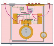
Rayma, this is what i understand from your suggestion, correct?
thanks..
Yes, and I would also use separate ground wiring for the volume control,
individually for both channels.
And also use a separate grounding wire for the source selector.
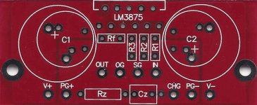
It appears that the data sheet and your pcb pinout IDs on the LM3875 differ.
Also, the data sheet lacks good application information.
What amp board are you using, and what is the CHG pin for?
Where are the large electrolytics, on the LM3875 pcb, or on the power supply board?
Last edited:
It appears to me from the OPs original image that the transformers are powering different circuits and only their primaries are in parallel.
If this is the case, then no problem.
If this is the case, then no problem.
It appears to me from the OPs original image that the transformers are powering different circuits and only their primaries are in parallel. If this is the case, then no problem.
If they were totally separate, then sure. They'd essentially be just two devices that happened to be inside the same box.
But I imagine there will have to be, at some point, a common ground point, and certainly a chassis ground. I think this might take some fooling around--or, hopefully, not.
.
If they were totally separate, then sure. They'd essentially be just two devices that happened to be inside the same box.
But I imagine there will have to be, at some point, a common ground point, and certainly a chassis ground.
I think this might take some fooling around--or, hopefully, not.
It's likely the the LV transformer secondary circuit is ungrounded,
but we'd have to see a schematic to be sure.
Guys, I really think you are over complicating this and trying to solve a problem that does not (as yet) exist.
I would simply connect signal out and ground from the source selector to signal in and ground on the chip amps.
I would simply connect signal out and ground from the source selector to signal in and ground on the chip amps.
Guys, I really think you are over complicating this and trying to solve a problem that does not (as yet) exist.
I would simply connect signal out and ground from the source selector to signal in and ground on the chip amps.
It's better to think these things through before construction, so you don't have to hack around so much.
Sometimes you might be lucky, but probably not.
Guys, I really think you are over complicating this and trying to solve a problem that does not (as yet) exist. I would simply connect signal out and ground from the source selector to signal in and ground on the chip amps.
I agree, there is such a thing as a solution looking for a problem. Still, I can imagine interesting but unwanted things happening.
All of which is merely speculation until, as has already been said, there's a full schematic.
I think maybe the correct approach might be to pretend that there are, in fact, two separate circuits, in two separate housings, and ground accordingly.
Although I can see problems with that too. Schematic needed.
.
Last edited:
Have a look at this Thread.
http://www.diyaudio.com/forums/chip-amps/273718-help-needed-wiring-amp-chassis.html
he/she has shown almost everything as PAIRS/Triplets.
Only the speaker circuits need to be paired to become correct.
Your layout breaks all the pairing rules.
It will be terrible trying to find why you have interference and even worse trying to cure it.
I prefer to separately fuse each transformer.
300VA on 230Vac would use a T1.25A fuse.
30VA on 230Vac would use a T250mA fuse.
Both of the above are effectively close rated, the 300VA using a soft start.
Imagine a catastrophic fault in the 30VA supplied circuit.
Imagine how long it would take for a T1.25A fuse to blow?
What if you did not use close rated fusing and adopted a T2.5A fuse for the Mains input?
How long will that fuse take to blow for a 30VA fault?
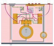
thanks everybody..
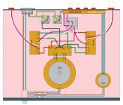
i need to clarify things, new chassis plan is below..
is it ok now?
and this is the source selector i put in to chassis..
4 in 1 Out Audio Pre Amp Input Relay Selector | eBay
boards are pretty standard Peter Daniel boards.. for more simplistic schema, i didn't include the caps..
i need to clarify things, new chassis plan is below..
is it ok now?
and this is the source selector i put in to chassis..
4 in 1 Out Audio Pre Amp Input Relay Selector | eBay
What amp board are you using, and what is the CHG pin for?
Where are the large electrolytics, on the LM3875 pcb, or on the power supply board?
boards are pretty standard Peter Daniel boards.. for more simplistic schema, i didn't include the caps..
that's ok but the ac inlet on rear panel has a fuse holder also. should i by-pass it or put a third fuse which has sum of total fuse value?I prefer to separately fuse each transformer.
i'm carefully twisting all pairs and triplets.. i did this way to keep to schema as simple as possible..Your layout breaks all the pairing rules.
Attachments
Unfortunately, separately fusing both transformers requires an earlier fuse to protect all the incoming cables....................that's ok but the ac inlet on rear panel has a fuse holder also. should i by-pass it or put a third fuse which has sum of total fuse value?.................
In the UK we used fused plug top at the wall socket. That could be the second line of protection. The first is the MCB/fuse in the distribution board.
The third line of defense are the transformer primary fuse/s
The rule is:
All cables fed by a fuse must be rated higher than the fuse rating.
This is where the 30VA falls over.
- Status
- Not open for further replies.
- Home
- Amplifiers
- Chip Amps
- Two transformers in one chassis