
That's the drains, not the drive, correct?
No. That was the PS. It was 27k, just like this.
I know that this may be annoying but if you don't provide reliable information, we're just going to go around in circles.
No. That was the PS. It was 27k, just like this.
I know that this may be annoying but if you don't provide reliable information, we're just going to go around in circles.
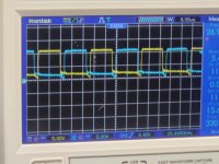
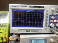
You are correct. That was the drain. Here's what it looks like before and after I put the fets in. The first pic is after
Attachments
Last edited:
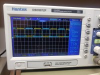
Does your hitachi work? Both channels?
I'd prefer not wasting time on a scope that sometimes works and other times gives bad waveforms. There is no advantage to using the digital scope.
I'd prefer not wasting time on a scope that sometimes works and other times gives bad waveforms. There is no advantage to using the digital scope.
Yes it works. I will use that from now on but u will need to tell me what settings for each measurement. I'm not to educated on scope use. I'm learning as I go.
A differential input uses two inputs to produce a single waveform. The simplest way to get a differential input is to use a differential probe. A differential probe has two signal leads and a mixer amplifier built into it. It feeds the scope a normal signal (a composite of the two signals input into the differential probe). The problem with differential probes is that they're expensive. The cheapest ones are about $60 used and they can cost more than $3000.
The alternative is to use two scope probes and and both inputs of your oscilloscope. This is how you have to set up your scope:
Two probes
Both scope inputs used
Input set to add
Both channels set to DC coupling
Both vertical amps set to the same voltage
Ch2 input set to invert
Bandwidth limited (works best for most measurements in car amps)
Trace aligned to the reference line on the scope's display
Ground leads for both probes connected together
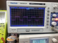
After setting up the scope, you need to confirm that it's working as it should. With the vertical amp set to 5v/div, touching the probe that's connected to Ch1 to the positive terminal of your 12v power supply should make the trace deflect about 2.5 divisions up from the reference (like it always does, seen below). Doing the same with the probe connected to Ch2 should make the trace deflect down about 2.5 divisions. Touching both probes to the positive terminal of the 12v power supply should cause no deflection. If it does, something isn't right.
I know that this may not be as simple as the isolated scope but if you take the time to learn it one time (even if it takes an hour or more of your time), you have that knowledge and this tool to use for the rest of the time you need to use a scope. Using the analog scope will give you much larger and cleaner waveforms.
The alternative is to use two scope probes and and both inputs of your oscilloscope. This is how you have to set up your scope:
Two probes
Both scope inputs used
Input set to add
Both channels set to DC coupling
Both vertical amps set to the same voltage
Ch2 input set to invert
Bandwidth limited (works best for most measurements in car amps)
Trace aligned to the reference line on the scope's display
Ground leads for both probes connected together
After setting up the scope, you need to confirm that it's working as it should. With the vertical amp set to 5v/div, touching the probe that's connected to Ch1 to the positive terminal of your 12v power supply should make the trace deflect about 2.5 divisions up from the reference (like it always does, seen below). Doing the same with the probe connected to Ch2 should make the trace deflect down about 2.5 divisions. Touching both probes to the positive terminal of the 12v power supply should cause no deflection. If it does, something isn't right.
I know that this may not be as simple as the isolated scope but if you take the time to learn it one time (even if it takes an hour or more of your time), you have that knowledge and this tool to use for the rest of the time you need to use a scope. Using the analog scope will give you much larger and cleaner waveforms.
Start with the PS gate drive. One probe on the source leg. One on the gate pad. The scope will be set to:
5v/div
10us/div
DC coupling
5v/div
10us/div
DC coupling
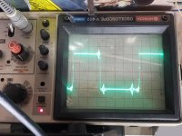
You have the probes backwards (locations). Reverse them and repost. Why did you go back to the other scope?

- Home
- General Interest
- Car Audio
- Twisted Sounds 8.5k