Was the black probe on the negative rail?
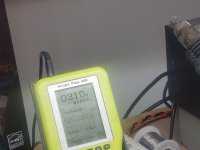
Where is the ground reference for the displayed waveform?
Where is the ground reference for the displayed waveform?
Set to DC coupling and place the black probe on the negative rail.
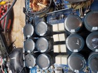
Everything on this IC is referenced to the negative rail except the high-side circuit (3 terminals).
Everything on this IC is referenced to the negative rail except the high-side circuit (3 terminals).
Idk. I was hoping u could tell me that.
Attachments

Last edited:
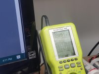
I think that drive signal is OK. It has an amplitude of about 7v.
Does your other scope show a square wave (perfectly square) when looking at the signal out of the PS driver IC?
Does your other scope show a square wave (perfectly square) when looking at the signal out of the PS driver IC?
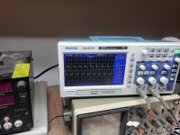
I'm gonna go off of what the hand held scope displayed. So why, when I put the fets in is there no switching?
Did you try adjusting the probe?
Install the FETs and when there is no drive what is the DC voltage on the output of the LM211?
Install the FETs and when there is no drive what is the DC voltage on the output of the LM211?
The 10k is only necessary when there is no feedback, like when the outputs are out of the circuit.
Do you have another probe?
Do you have another probe?
Try adjusting it on the drive signal of the PS driver IC to see if it looks better on the waveforms in the output section.
- Home
- General Interest
- Car Audio
- Twisted Sounds 8.5k