Using neg rail as ground pin 2 is at -4.64vdc
I do not see any signal on the output of the tl072 or the lm311
Yes 4 fets total
I do not see any signal on the output of the tl072 or the lm311
Yes 4 fets total
Do you have the probes plugged in/placed properly? It would be odd to be negative when the negative rail is the lowest point in the amp.
Remove the FETs and connect a 10k resistor between terminals 1 and 2 of the TL072 on the driver board. Drive a 100Hz signal into the amp and check for audio up to the input of the 21844s.
Adjust the level so that the output of the TL072 isn't clipping. Do you have a relatively clean sine wave out of the TL072?
What is the DC voltage on the output of the TL072?
Adjust the level so that the output of the TL072 isn't clipping. Do you have a relatively clean sine wave out of the TL072?
What is the DC voltage on the output of the TL072?
Last edited:
With the gain all the way down the signal looks is clipped so bad it looks like a squarewave almost
I pulled the driver card out. When I feed it a 100hz sinewave shouldnt I be able to see the signal on one of the pads for the driver card?
#47:
I can't tell you the exact signal level to use. Reduce it until the output of the TL072 is no longer clipping. Did you install the 10k resistor?
If the TL072 was showing signal, the signal was reaching the driver board. Are you looking for signal with the driver board out of the circuit?
I can't tell you the exact signal level to use. Reduce it until the output of the TL072 is no longer clipping. Did you install the 10k resistor?
If the TL072 was showing signal, the signal was reaching the driver board. Are you looking for signal with the driver board out of the circuit?
I put the 10k resistor across pins 1 & 2 of the tl072 chip and shorted pins 2 & 3 of the irs21844s chips and saw signal on pin 1. 100hz but it was a squarewave.
Last edited:
Pin 1 generally but on some driver boards it's pin 7. Which one had a clipped signal?
If the signal is on pin 7, the 10k resistor needs to be connected between pins 6 and 7.
If the signal is on pin 7, the 10k resistor needs to be connected between pins 6 and 7.
Last edited:
What's the DC voltage on pin 7?
Do you have a square wave swinging from +5v to -5v on the output of the LM211?
Do you have a square wave of about 10v amplitude (referenced to the negative rail) on the input of the 21844s?
Do you have a square wave swinging from +5v to -5v on the output of the LM211?
Do you have a square wave of about 10v amplitude (referenced to the negative rail) on the input of the 21844s?
There is 0v dc on pin 7 of the tl072
Yes there is a ac squarewave swinging from +5 to -5 on the output of the lm311
I have a squarewave on the input of the irs21844s but it's only 3vac
Yes there is a ac squarewave swinging from +5 to -5 on the output of the lm311
I have a squarewave on the input of the irs21844s but it's only 3vac
Are you saying that is only swings from the negative rail to 3v above the negative rail? What's the amplitude as seen on the scope?
Does it go all of the way back down to the negative rail?
Does it go all of the way back down to the negative rail?
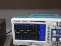
Your scope is on AC coupling so 'below' is meaningless. You need to have the DC component included for drive signals. That's why using the scope in differential mode or using an isolated scope (handheld) is important.
You can shift the trace but when you do that, you have to also display or make note of the rail voltage for the waveform to be useful.
The shape of the waveform is not good. It should be very nearly perfectly square.
You can shift the trace but when you do that, you have to also display or make note of the rail voltage for the waveform to be useful.
The shape of the waveform is not good. It should be very nearly perfectly square.
- Home
- General Interest
- Car Audio
- Twisted Sounds 8.5k