To say we haven't communicated the intent, that is one thing. Sometimes it takes more than one post to understand... but these words I've quoted, I don't understand.
I didn't mean to include you specifically in that, sorry!
It looks like the chart is labelled backwards though
not sure what you mean. in the graph you see amplitude and impedance of tweeter with cap (plus resistor for the red graphs).
impedance is very high at lower frequency because of the cap.
I don't know what it is about the DT94 that allows for such a mild impedance peak, but I wish more tweeters were like it. I don't think it's the ferrofluid doing most of the damping because Qes is 0.66 and Qts is 0.54.
mild impedance peak is definitely because of ferrofluid. have a look at my attached measurements of a tweeter before and after removal of ferrofluid.
Attachments

Last edited:
not sure what you mean. in the graph you see amplitude and impedance of tweeter with cap (plus resistor for the red graphs).
impedance is very high at lower frequency because of the cap.
sorry, you are right, of course: red graph is without resistor, black is with resistor!
Listen Amigo, you sound like a badly educated, up his back side pretentious person....
+1
Earlier, somebody used the term "fry" the tweeter for tweeters with their resonance within the passband, as a badly educated person might be inclined to favour.
mike7877 thought that meant over-heat and on finding his tweeter not too hot to touch, diss'ed the notion.
A better term than "fry" would be over-drive and damage which could certainly happen to some fragile drivers with real shallow slope XO (like a single cap. even an octave or more spaced away) and an anti-damping resistor in series.
I also note mike7877 uses the term "critical" damping. There's nothing special, advantageous, or critical about that Q for audibility, just convenient for doing the math.
B.
Last edited:
+1
Earlier, somebody used the term "fry" the tweeter for tweeters with their resonance within the passband, as a badly educated person might be inclined to favour.
mike7877 thought that meant over-heat and on finding his tweeter not too hot to touch, diss'ed the notion.
A better term than "fry" would be over-drive and damage which could certainly happen to some fragile drivers with real shallow slope XO (like a single cap. even an octave or more spaced away) and an anti-damping resistor in series.
I also note make7877 uses the term "critical" damping. There's nothing special, advantageous, or critical about that Q for audibility, just convenient for doing the math.
B.
Since the driver's natural rolloff is being used as the crossover point to a woofer which is low passed 2nd order, having its q remain near 0.5 is preferable. If both the woofer and tweeter are the same amplitude, having their slopes match (q0.5, critically damped) will result in the flattest frequency response. And there will be no ringing. If I'm wrong, tell me how I'm wrong so I can learn. Educate me 🙂
Edit: as mentioned previously I did a pink noise power test for half an hour and the dome didn't even heat up a single degree. Measured with IR thermometer. Also as mentioned previously the speaker will be used quietly most of the time. I understand the configuration I've chosen is bad practice for mains speakers dedicated to music.
Edit: you presume to know what I know and put words in my mouth. I don't even know how you assume the things you do from the things I've said. I'm not formally trained in the art of speaker design and never claimed to be. But I'm not clueless and do have some specific knowledge which others on or visiting this forum may be able to learn from while reading these discussions. Someone in the future may want to use a tweeter's rolloff as crossover, this thread will contain pertinent info for them to succeed. So please correct the first paragraph if you think I'm wrong, and if not, don't clutter
Last edited:
mild impedance peak is definitely because of ferrofluid. have a look at my attached measurements of a tweeter before and after removal of ferrofluid.
I guess it can vary depending on the suspension. I've never seen such an extreme example as yours. My mental point of reference previously is the wavecor tweeters which come in ferrofluid/non ferrofluid versions , their peaks are reduced 20% or so with the ferrofluid
Stv, it'd be interesting to see how harmonic distortion is affected by q. The easiest experiment would be a woofer being put into progressively smaller enclosures. Higher q's must increase 2nd harmonic distortion at least. Maybe this is why a lot of tweeters have increased harmonic distortion around resonance: the increased amplitude comes from somewhere - counter force being applied to the diaphragm?
Stv, it'd be interesting to see how harmonic distortion is affected by q.
i'm not aware of Q as such affecting distortion.
distortion is mainly caused by motor and suspension non-linearity, which you will probably experience when driving the tweeter at or below resonance frequency.
but, as I said: harmonics can sound good, so it may be perfectly ok for you.
regarding your proposed experiment: a smaller enclosure will even reduce distortion by reducing the voice coil excursion (distorsion measured as absolute amount, relative may be different for some frequencies, as a small enclosure will reduce low frequency output). spring force of compressed or expanded air is quite linear compared to a voice coil leaving the magnet field or a surrond being driven to the limit.
I've never seen such an extreme example as yours.
yes, the ferrofluid in the tweeter i measured was old and slightly dried-out, so this example is definitely extreme ...
Last edited:
a smaller enclosure will even reduce distortion by reducing the voice coil excursion
The reduction of excursion with smaller boxes is only partially true - for frequencies below resonance, say an octave or so, it's true: a smaller box will reduce excursion. But not frequencies at or slightly above resonance.
With bass it's usually the lower frequencies at about 50hz which cause problems for 5-6 inch drivers with say a 70hz resonance. The woofer in a smaller enclosure with a higher q when given a higher frequency at around or slightly above resonance, would have a higher excursion at lower power - ~100hz in this example. It would also have lower excursion at 50hz.
Think about it this way, the increased amplitude at or above resonance from an increased q can only come from increased excursion in a sealed design (no port interaction amplifying anything). 100hz doesn't usually give problems for any woofer as there's usually less energy there and even if it was the same, excursion for it is just 1/4 of what's required for 50hz. But we are talking about a 0.8" tweeter
Since we're talking crossing tweeters low, mid band energy isn't like bass and the analogy isn't applied quite as easily, but think about it though.
Anyway, I'm not thinking harmonic distortion from increased excursion around resonance, just from the driver being undamped.
You say the acoustic suspension is quite linear, so maybe it's be third harmonic distortion that's higher with a higher q (2nd harmonic one way (in), 3rd the other way (out)).
Horribly organized but I'm on my phone. I think it's clear what I'm getting at
Last edited:
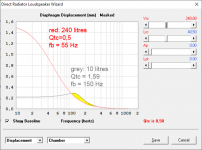
The reduction of excursion with smaller boxes is only partially true - for frequencies below resonance, say an octave or so, it's true: a smaller box will reduce excursion. But not frequencies at or slightly above resonance.
you are right. it's not very much, though. see my simulation for a woofer in a 10 liter and a 240 liter closed box with Qtc 1,59 and 0,5 respectively. the yellow area is where the smaller box leads to higher excursion.
Anyway, I'm not thinking harmonic distortion from increased excursion around resonance, just from the driver being undamped.
why should dampening of a speaker affect harmonic distortion, if we exclude non-linearity of suspension or motor?
it will affect linear distortion (frequency response) but not harmonic distortion.
Attachments
To understand what I was thinking imagine a driver reaching the mechanical limit of its excursion. Not violently, but the spider and surround being fully extended. The driver very quickly stops in two places it should continue, altering the waveform into a stretched square wave with added harmonics. I was thinking maybe the air surrounding the dome of a tweeter with Vas of like 5mL could have a similar effect, but after some consideration now it seems the effect would be minimal, almost immeasurable
Last edited:
The driver very quickly stops in two places it should continue, altering the waveform into a stretched square wave with added harmonics.
the waveform will probably not be "cut off" as it happens with a hard clipping amplifier, but the peaks will rather be gradually be compressed, resulting in "mild" harmonic distortion. or, in other words, if the diaphragm, suspension or voice coil is really stopped hard it will very quickly be damaged beyond repair.
that's why some speaker manufacturers define "Xmax" and "Xlim" (or "Xdamage").
what many try to explain is that with your low crossover frequency you will easily drive the tweeter into "Xlim" and damage the driver.
I was thinking maybe the air surrounding the dome of a tweeter with Vas of like 5mL could have a similar effect, but after some consideration now it seems the effect would be minimal, almost immeasurable
air has good compression linearity, compared to any suspension or magnet field. so why should it, at any point, stop the diaphragm abruptly ("very quickly")?
non-linearity of air may be an issue for extremely high SPL horn drivers, but not a small surround speaker tweeter...
air has good compression linearity, compared to any suspension or magnet field. so why should it, at any point, stop the diaphragm abruptly ("very quickly")
Think of compressing a bike pump with its valve blocked - it's pretty easy to compress the first half or two thirds of the way, then quite suddenly, significant resistance. I do think the point this would happen with a dome tweeter is far beyond xmax/xlim now though
About damage, this 0.8" tweeter's capacitor filters from half an octave below resonance (so no increased excursion from it) and its rolloff is 2nd order from 1700hz, 3rd from 1300hz with an xmax of 0.25mm, 0.5p-p. It's not a high power design, but it shouldn't be easily damaged either. What also helps limit damage is the underhung design, BI drops quite quickly once the coil leaves the gap. It should take a lot of power to force it out far enough that damage is done. I think the designs more to be concerned with have crossover points above their resonances which are around 800hz, and impedance peaks 100-200% higher than nominal and no impedance flattening measures. That I can see causing dangerous excursion.
Air non-linearity is usually only a concern with reflex ports.
Good to know!
Last edited:
Hi all.
System7 did it well !
I attenuated (by -3.3dB) this tweeter on my crossover (12-18dB/oct) using two resistors, 15 ohms and 2.2 ohms, but the harshness persisted.
So I tried what user system7 was talking about on the first page.
I paralleled 7R5+ 1u5 for the tweeter (Visaton DT94).The result is very, very good.
Thank you system7.
Jan

Thank you EarlK 🙂
I have to do the same thing for my Vifa-Mirage 5DR51441, but I have to count RC values again.
But the harshness in this tweeter is very small.
It was very cheap tweeter, but it sounds excellent anyway.
If someone needed help with RC compensation (IN PARALLEL WITH THE TWEETER):
(Do it only at your own risk, I´m not responsible for any damage you could do to your equipment)
----------------------------------------------------------------------------------------
Re (woofer/midrange/tweeter)....... (you can find it in datasheet or you can use multimeter)
Le (woofer/midrange/tweeter).........(you can find it in datasheet (it is in mH !) or you can use multimeter)
R = Re + Re/2 (in Ohms)
C = Le [H] / R² (In Farads, so don’t forget to convert it to uF..... x 1 000 000)
The RC values for the Zobel circuit could be slightly smaller.
--------------------------------------------------------------------------------------------
J.
Last edited:
But maybe this is better formula for R :
R = Re x 1,25
But you can find two versions on the internet.
R = Re x 1,25
But you can find two versions on the internet.
I have got one question now.
If I had two midranges (4 Ohms) connected in series, how I would count this Zobel network?
Is it OK like this?
Re total = Re1+ Re2
Le total = Le1+Le2
C = Do I have to cut the value of the capacitor in half?
Thank you.
J.

If I had two midranges (4 Ohms) connected in series, how I would count this Zobel network?
Is it OK like this?
Re total = Re1+ Re2
Le total = Le1+Le2
C = Do I have to cut the value of the capacitor in half?
Thank you.
J.
- Home
- Loudspeakers
- Multi-Way
- Tweeter Q change with series resistor for attenuation?