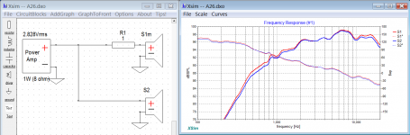
Basta!
Yes, that's the name of that piece of software, Svante, the author is a member here.
Your tweeter's Fs is quite high - 1.9kHz. It needs to be crossed at least an octave higher than Fs.
Your XO point is quite low.
You will fry the VC of the tweet very quickly, the cap will not save it from excessive excursion, only from DC.
1 ohm resistor will have minuscule influence on the Q of the filter, not sure why you are worried about Q there.
Basta!
Yes, that's the name of that piece of software, Svante, the author is a member here.
Your tweeter's Fs is quite high - 1.9kHz. It needs to be crossed at least an octave higher than Fs.
Your XO point is quite low.
You will fry the VC of the tweet very quickly, the cap will not save it from excessive excursion, only from DC.
1 ohm resistor will have minuscule influence on the Q of the filter, not sure why you are worried about Q there.
I tested with pink noise at a level just below peaks for 30 minutes, temperature of the dome didn't even rise 1 degree Celsius. Also, no audible distortion. Xmax is .25mm, 0.5 p-p. Tweeter will be fine. And should sound fine being critically damped. I stated this wasn't an issue in the original post.
Edit: if you look at the frequency response of the tweeter (or just consider q is 0.5 and fs is 1900hz) excessive excursion is prevented by itself, leaving heat the only issue. With the cap on the tweeter filtering from 1300hz, the tweeter gets 1/4 power at 650hz, 1/16 power at 325hz, 1/64 the power at 162.5hz, and 1/256 the power at 80hz. Since the woofer is just 40wRMS, you can see that heat won't be an issue for the tweeter
Last edited:
To clarify Stanislav, I'm not concerned the effect the resistor has on the q of the filter (capacitor), I'm concerned the effect it has on the q of the driver. At 1300hz, the driver is already down 5 or 6db, so if the slope from there is slightly off, the effect is minimal and quickly becomes completely inconsequential. The capacitor is actually detrimentally affecting the phase of the last half of the octave of the driver's natural roll off I'm using as the crossover point. No big deal to me if it's slope changes a bit. I'm aware there will be a bit less energy between ~850 and 1300hz, probably somewhere around a decibel between 1050 and 1300hz - I'm not worried. Much worse would be a problem in the first 6db
The Q of the tweet will change because of the series cap. You'll have a huge peak at Fs and instead of reduction of output the excursion will go through the roof. You'll have to either apply an LRC across the driver to tame that peak, or increase the XO frequency. I would employ a Series XO and still at least double the cut-off point.
You have options and it's up to you which way you want to go.⁵
You have options and it's up to you which way you want to go.⁵
The Q of the tweet will change because of the series cap. You'll have a huge peak at Fs and instead of reduction of output the excursion will go through the roof. You'll have to either apply an LRC across the driver to tame that peak, or increase the XO frequency. I would employ a Series XO and still at least double the cut-off point.
You have options and it's up to you which way you want to go.⁵
There is virtually no impedance change at resonance. Also, the cap is well below resonance. As mentioned in OP
I chose this tweeter specifically to use its natural rolloff as the crossover point. I didn't expect to need to attenuate it, as its sensitivity matches the woofer (chosen for this as well). My question was about series resistance changing the tweeter's Q. Anyway, moving the crossover point up to 4khz disables perfect horizontal dispersion to 70 degrees through the critical 2-3khz range (yes this is a requirement because of position). Especially not happening with the woofers low resistance air core inductors and film caps for 1700hz already being installed.
Besides, your advice doesn't apply. It might in a lot of cases, but that doesn't excuse you not reading my carefully constructed original post partially designed to filter out irrelevant suggestions like yours
Last edited:
I have an unusual question, unlike most -an opportunity to exercise the mind share new knowledge, not just spouting the same thing over and over again to the same questions asked over and over again by people averse to search. But I still don't have an answer
Sorry to sound like I'm complaining, but the purpose of forums is to accumulate and share knowledge
Sorry to sound like I'm complaining, but the purpose of forums is to accumulate and share knowledge
Last edited:
How are you going to induce ringing?Most importantly, will I induce ringing in the tweeter by adding series resistance while using its natural rolloff (q~0.5) as the crossover point?
Besides, your advice doesn't apply. It might in a lot of cases, but that doesn't excuse you not reading my carefully constructed original post partially designed to filter out irrelevant suggestions like yours
Nice!
How are you going to induce ringing?
To my knowledge, after adding resistance between an amplifier and driver, Qts doesn't equal Qtc anymore. This tweeter's Qts is 0.54, basically critically damped, which to my knowledge, makes it optimal for integration with a linear phase 2nd order low passed woofer of the same sensitivity, provided the frequencies match.
I assume that tweeters, like woofers, get a notable bump in response and some ringing when Q approaches 1.2-1.5. I'm just wondering how much of an effect a series resistor of say an ohm or two (if I add one, to answer your question) would have on the tweeter's Qtc
Last edited:
Nice!
To be fair I said it in my original post, and then I told you twice. And then I was a bit short at the end of explaining it the third time.
There it is again to someone else in the post above this one! And I'm sure it's in there 3 or 4 more times in between too.
It's kind of funny lol
Last edited:
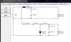
I have taken the trouble of simming something resembling your speaker for you, in visaton boxsim, applying "the standard model" of loudspeakering. 😀
I don't know what your speaker sounds like with the unspecified first order capacitor tweeter crossover and unspecified bass filter, so it's all a shot in the dark. I certainly don't think much of your idea without considerably well-behaved drivers, which yours probably aren't! My efforts with single capacitor and 6" were plain hopeless. Nothing worked right. 😱
All turns out quite conventional. I show the effect of the 8.2R/1.5uF Zobel in taming the DT94. How it sounds only time will tell. Some of the values marked in red might be adjust to taste. I did it 16L closed box. 23cm wide baffle. Hope it helps.
Attachments
To be fair I said it in my original post, and then I told you twice. And then I was a bit short at the end of explaining it the third time.
There it is again to someone else in the post above this one! And I'm sure it's in there 3 or 4 more times in between too.
It's kind of funny lol
Listen Amigo, you sound like a badly educated, up his back side pretentious person.
This forum is not here to answer your "carefully crafted" questions but to create a community and encourage dialog, exchange of ideas and most of all be fun.
If you did not like my answers you could just ignore them, not telling me off cause you did not like what I said.
It is not only rude but also arrogant and stupid.
Not sure how young or old are you but looking at the date you joined in - April 2021, you are quite fresh.
Maybe you should learn to show some respect here and there before asking others to chime in.
I have taken the trouble of simming something resembling your speaker for you, in visaton boxsim, applying "the standard model" of loudspeakering. 😀
I don't know what your speaker sounds like with the unspecified first order capacitor tweeter crossover and unspecified bass filter, so it's all a shot in the dark. I certainly don't think much of your idea without considerably well-behaved drivers, which yours probably aren't! My efforts with single capacitor and 6" were plain hopeless. Nothing worked right. 😱
All turns out quite conventional. I show the effect of the 8.2R/1.5uF Zobel in taming the DT94. How it sounds only time will tell. Some of the values marked in red might be adjust to taste. I did it 16L closed box. 23cm wide baffle. Hope it helps.
Thanks for the effort. It sounds good with a top end that's a little bright. The filter on the woofer is 2nd order 1700hz to match the tweeter's natural roll off, 2nd order 1700hz q 0.54 (previously mentioned). The capacitor is not for crossover, it's half an octave below the natural rolloff (crossover point) for the purpose of blocking LF energy only (preventing the heating of the tweeter's voice coil). The tweeter's impedance only rises ~10% at resonance.
The woofer is very well behaved, flat 1.5 octaves past xover and perfectly wide dispersion to 80 degrees up to 1700hz (required for speaker position in room). I might add a circuit to flatten impedance to improve phase as well, but that's not my question.
My question is, if I add an ohm or two between the tweeter and amplifier, what would it's q change to? There's more relevant information in the original post and through the thread, I've said what I posted here many times over already. Please read, I'd appreciate your help
Listen Amigo, you sound like a badly educated, up his back side pretentious person.
This forum is not here to answer your "carefully crafted" questions but to create a community and encourage dialog, exchange of ideas and most of all be fun.
If you did not like my answers you could just ignore them, not telling me off cause you did not like what I said.
It is not only rude but also arrogant and stupid.
Not sure how young or old are you but looking at the date you joined in - April 2021, you are quite fresh.
Maybe you should learn to show some respect here and there before asking others to chime in.
I'm here to learn and have fun. I've been nothing but respectful and patient. I keep getting irrelevant information from people who hadn't bothered to read even my original post in any detail - almost 3 pages of it! Of course at at point I have to call attention to the fact, if anything's to change. Since youre so educated, maybe you could answer my question
Last edited:
To say we haven't communicated the intent, that is one thing. Sometimes it takes more than one post to understand... but these words I've quoted, I don't understand.I keep getting irrelevant information from people who hadn't bothered to read even my original post in any detail
To my surprise, I found a lot to like in your low crossover design after some effort, Mr. Mike. 😱
I usually consider single capacitor filters to be foolish nooby monkey business, but here found things to like. 🙂
John Devore names all his speakers after monkeys, here a Gibbon, and is no mug:

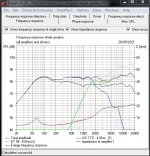
You have my blessing to add a resistor in series with your capacitor, and for sure it won't be worse! Any little blips around 3-4kHz are certainly diffraction effects. I simmed it with and without the resistor. Whether you want to further monkey around with offset tweeters to fix the diffraction, and inverted basses is up to you.
Being a bit 90 degree Butterworth, your speaker has excellent flat power response at crossover. I think it might sound very good slightly off-axis too, without any offset.
I usually consider single capacitor filters to be foolish nooby monkey business, but here found things to like. 🙂
John Devore names all his speakers after monkeys, here a Gibbon, and is no mug:
You have my blessing to add a resistor in series with your capacitor, and for sure it won't be worse! Any little blips around 3-4kHz are certainly diffraction effects. I simmed it with and without the resistor. Whether you want to further monkey around with offset tweeters to fix the diffraction, and inverted basses is up to you.
Being a bit 90 degree Butterworth, your speaker has excellent flat power response at crossover. I think it might sound very good slightly off-axis too, without any offset.
Attachments
when measuring tweeters i noticed that they have significantly higher harmonic distortion around and below the resonance frequency. dome tweeters only have a single simple suspension (no spider, only surround) and thus tend to wobble at lower frequencies. harmonic distortion can actually sound good, so maybe you are ok with that.
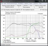
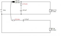
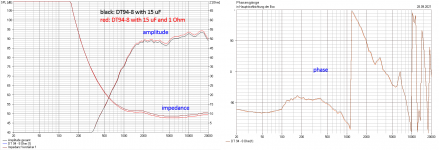
i suppose your cap has about 15 uF, this will limit the max power to the tweeter to about 20 watts at 1,5 kHz (limit by max excursion).
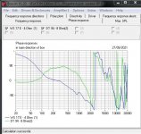
attached you find the (simulated) change if you insert a 1 ohm series resistor to the 15 uF cap somewhere in the tweeter connection.
the simulation was done in visaton's boxsim-software, assuming an arbitrary baffle, so exact freqency response will be different in your case.
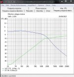
- phase change is barely visible.
- impedance gets higher by ~ 1 ohm in passband area.
- amplitude is lowered by ~ 1,5 dB.
DT94 has a low Qts mainly because of ferrofluid dampening. this results in a low impedance peak at resonance frequency. as you can see the 1 ohm resistor does not change the peak at all, besides the general increase in impedance by 1 ohm - so no significant change in Q.
i suppose your cap has about 15 uF, this will limit the max power to the tweeter to about 20 watts at 1,5 kHz (limit by max excursion).
attached you find the (simulated) change if you insert a 1 ohm series resistor to the 15 uF cap somewhere in the tweeter connection.
the simulation was done in visaton's boxsim-software, assuming an arbitrary baffle, so exact freqency response will be different in your case.
- phase change is barely visible.
- impedance gets higher by ~ 1 ohm in passband area.
- amplitude is lowered by ~ 1,5 dB.
DT94 has a low Qts mainly because of ferrofluid dampening. this results in a low impedance peak at resonance frequency. as you can see the 1 ohm resistor does not change the peak at all, besides the general increase in impedance by 1 ohm - so no significant change in Q.
Attachments
Last edited:
this will limit the max power to the tweeter to about 20 watts at 1,5 kHz (limit by max excursion
I should rather say: you need to limit the power to 20 W around 1,5 kHz to avoid damaging the tweeter by over-excursion.
Thank you system7 and stv. It seems the resistor should be fine 🙂
system7, I can't offset the tweeter at all because the speaker is in wall - I replaced drivers in a pre existing enclosure). But I don't need to move it, the sound is good in the listening position, as well as most other places in the room. Because the listening position is about 50 degrees off centre, I'm thinking of leaving the brighter top end (no zobel) because at the listening position the top octave sounds fine, maybe even a little soft.
stv, glad to see the resistor doesn't affect the frequency response, very good news! It looks like the chart is labelled backwards though
I don't know what it is about the DT94 that allows for such a mild impedance peak, but I wish more tweeters were like it. I don't think it's the ferrofluid doing most of the damping because Qes is 0.66 and Qts is 0.54.
These speakers are just surrounds - they won't be played too loud. It should be fine if the occasional transient causes the tweeter to reach xmax because it's an underhung design (2.0mm VC, 2.5mm plate) so damage shouldn't result. At the levels they'll be used, xmax should only very rarely be reached
Last edited:
- Home
- Loudspeakers
- Multi-Way
- Tweeter Q change with series resistor for attenuation?