Hi,
Would it be possible to make this work with an original Linn Lingo 4 switch? I only have the switch, so would be nice to be able to use it and have 2 different leds for speed indication. Here is a description of how this switch works:
Switch Operation:
When the LP12 is powered off, a short single press of the LP12 switch will start the deck on 33 rpm mode
When the LP12 is running, a short single press of the switch will change the speed between 33 rpm and 45 rpm
When the LP12 is running, a long press and hold of the switch will power off the LP12
Rob.
Attachments
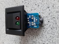
Hi Rob, you can use the Lingo switch as long as its a momentary action like the Valhalla switch. Currently it works as follows:
Switch Operation:
When the LP12 is powered off, a short single press < 0.5s of the LP12 switch will start the deck on 33 rpm mode
When the LP12 is running, a single press of 3s (LED flashes) the switch will change the speed between 33 rpm and 45 rpm
When the LP12 is running, a long press >1s <3s and hold of the switch will power off the LP12
There is only one LED output though so you wont be able to use both LED's unfortunately.
I do have the right square switches available to fit the Linn LP12 with bezel and single LED (see earlier posts). They are 18GBP each.
Hi,
Would it be possible to make this work with an original Linn Lingo 4 switch? I only have the switch, so would be nice to be able to use it and have 2 different leds for speed indication. Here is a description of how this switch works:
Switch Operation:
When the LP12 is powered off, a short single press of the LP12 switch will start the deck on 33 rpm mode
When the LP12 is running, a short single press of the switch will change the speed between 33 rpm and 45 rpm
When the LP12 is running, a long press and hold of the switch will power off the LP12
Rob.
Thanks for the reply. I guess it is probably easier to use the switch from the Valhalla I have in my LP12 now. I am interested in this controller, not sure which option would be best. I have never soldered smd before. Is the manual available somewhere, or only after ordering?
Updates
Hello fellow DIYers and Motor Controller devotees.
A positive development. A batch of PCB’s arrived last week and I have started on the assembly of the SMD components (I have all of those). As mentioned previously still short of a couple of through hole components and some of the hardware. However, I have found a couple of spare PSU chips and similar size heatsinks in my stock (with a little bit of trimming I can make them fit). They will go out to a small advance party who will test out the instructions before they go out to the wider group.
One or two participants of the group buy have contacted me not realising there were SMD components. From the first prototype pictures posted the number of SMD components has increased:
1. All resistors are now SMD.
2. The 1N4148 signal diodes are now SMD
3. The NPN/PNP signal transistors are now SMD
4. There is at least one 1mm pitch FFC connector option added.
Just to explain the rationale behind these changes:
As over half of the resistors were SMD anyway there was not much point in keeping through hole versions with having to bend and crop leads. Keeping one kind of resistor (SMD) made ordering simpler. In addition, there was a request to make the bearing hole larger. This meant saving more space on the board. If you can solder hand solder SMD 1206 resistors you can also hand solder the SMD diodes and SMD signal transistors. All you need is a fine tipped soldering iron, tweezers and reasonable near field eye sight. The manual gives you the technique on how to hand solder SMD. (An SMD flux pen is beneficial but not essential).
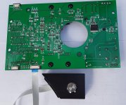
I also improved the electrical noise from the PSU. This meant adding extra components. These had to go on the underside.
As previously mentioned to make the thinnest possible cable an FFC cable was chosen to connect the assembled units to the combined speed sensor box. Soldering this is tricky and it’s different from the prototype. At 1mm pitch its quite fine and pushing the limits of hand soldering – hence why I am going to add that to the board, soldered, for everyone who has ordered a kit so you can take advantage (even though the original 0.1” pin header still exists).
If you have ordered a kit and are having second thoughts regarding SMD soldering, contact me via PM and I will change your order to an assemble version.
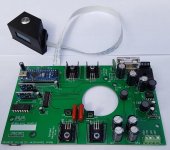
The images show completed underside, topside and the new FFC cable attached on the boards I built this weekend.
Hello fellow DIYers and Motor Controller devotees.
A positive development. A batch of PCB’s arrived last week and I have started on the assembly of the SMD components (I have all of those). As mentioned previously still short of a couple of through hole components and some of the hardware. However, I have found a couple of spare PSU chips and similar size heatsinks in my stock (with a little bit of trimming I can make them fit). They will go out to a small advance party who will test out the instructions before they go out to the wider group.
One or two participants of the group buy have contacted me not realising there were SMD components. From the first prototype pictures posted the number of SMD components has increased:
1. All resistors are now SMD.
2. The 1N4148 signal diodes are now SMD
3. The NPN/PNP signal transistors are now SMD
4. There is at least one 1mm pitch FFC connector option added.
Just to explain the rationale behind these changes:
As over half of the resistors were SMD anyway there was not much point in keeping through hole versions with having to bend and crop leads. Keeping one kind of resistor (SMD) made ordering simpler. In addition, there was a request to make the bearing hole larger. This meant saving more space on the board. If you can solder hand solder SMD 1206 resistors you can also hand solder the SMD diodes and SMD signal transistors. All you need is a fine tipped soldering iron, tweezers and reasonable near field eye sight. The manual gives you the technique on how to hand solder SMD. (An SMD flux pen is beneficial but not essential).
I also improved the electrical noise from the PSU. This meant adding extra components. These had to go on the underside.
As previously mentioned to make the thinnest possible cable an FFC cable was chosen to connect the assembled units to the combined speed sensor box. Soldering this is tricky and it’s different from the prototype. At 1mm pitch its quite fine and pushing the limits of hand soldering – hence why I am going to add that to the board, soldered, for everyone who has ordered a kit so you can take advantage (even though the original 0.1” pin header still exists).
If you have ordered a kit and are having second thoughts regarding SMD soldering, contact me via PM and I will change your order to an assemble version.
The images show completed underside, topside and the new FFC cable attached on the boards I built this weekend.
Attachments
I think for me, a built and tested unit would be best. I would like to place it inside the LP12 and use the Valhalla switch.
Ok that's fine. Can you fill out the Google form posted in earlier posts and I will add you to the second group buy.
I think for me, a built and tested unit would be best. I would like to place it inside the LP12 and use the Valhalla switch.
I just filled out the google form. Is the holder for mounting the sensor inside the platter also included? Would be nice to have both options.
Hi Steve.
Is the reason the bearing hole was made larger was to enable the the new Linn Karousel bearing to be fitted?
Is the reason the bearing hole was made larger was to enable the the new Linn Karousel bearing to be fitted?
Hi Raymond, exactly that.
Regards, Steve
Regards, Steve
Hi Steve.
Is the reason the bearing hole was made larger was to enable the the new Linn Karousel bearing to be fitted?
Hi Raymond, exactly that.
Regards, Steve
Thanks for the info Steve, I thought that was the reason!
Although at £750! I'll pass!😱
Regards
Ray
Update
Hello fellow DIYers and Motor Controller devotees.
This week’s updates. I am still waiting for the final few components. However, all SMD components are soldered and ready on the fully assembled kits. The next process will be to assemble the through hole larger components. For the parts kits, they are all ready apart from the last few missing items.
The advance party kits/fully assembled units have been despatched.
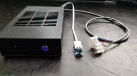
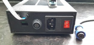
Also attached is a view of the 3D printed external enclosure. I can confirm the SP13 connectors mentioned in the previous posts are good and the correct genders.
The missing PCB’s actually did turn up this week so as it turns out paying for an express DHL shipment turned out to be a waste of time.
Hope everyone is well and not too fed up with the various lock downs.
Hello fellow DIYers and Motor Controller devotees.
This week’s updates. I am still waiting for the final few components. However, all SMD components are soldered and ready on the fully assembled kits. The next process will be to assemble the through hole larger components. For the parts kits, they are all ready apart from the last few missing items.
The advance party kits/fully assembled units have been despatched.
Also attached is a view of the 3D printed external enclosure. I can confirm the SP13 connectors mentioned in the previous posts are good and the correct genders.
The missing PCB’s actually did turn up this week so as it turns out paying for an express DHL shipment turned out to be a waste of time.
Hope everyone is well and not too fed up with the various lock downs.
Attachments
Last edited:
That looks great! Would it be possible to have and AC inlet and AC outlet? Effectively putting the controller inline of the power to the motor?
Looking really good there. I've just fitted a nice Hirose socket and plug to my DIY geddon, quite costly but think I'll use one here too for a good 'quality' feel.
Hi DarPhyve, the reason it's a multipole connector is that the controller outputs two completely seperate AC signals that are offset by an adjustable phase difference which you usually start at about 90 degrees. You wire the AC synchronous motor in your turntable directly to this controller. That results in best drive conditions and lowest noise from your motor.
What you will find in your turntable at the moment is a small pcb that splits the incoming AC into two phases by an RC (or CC) network. This is never exact due to component tolerance.
This controller board improves on that process by generating the sinewaves independently at 0.001Hz resolution with adjustable voltage, frequency and phase characteristics. You start with the default settings on the board then make phase and voltage adjustments to get your motor running as quiet as possible.
Note: true sinewave are produced by DDS generators. Its not a square wave to sinewave conversion.
When adding a sensor and PID control it provides very accurate speed control at 33.33x or 45.00x where the 3rd DP typically sees small fluctuation. The board does this by calculating the correct frequency to drive the motor based on feedback from the rpm sensor.
I have tried this boards on several Linn LP12's and different makes of turntable and they all run at different speeds. Most Linns even with Valhallas run at 33.4 rpm and fluctuate quite a bit. Causes of this are motor tolerance, belt/bearing wear, stylus drag, varying mains frequency etc.
What I observed in actually listening is that the timing of the music just really locks in.
So hopefully you see that to put a single AC output (Although possible) negates many of the benefits of driving the motor phases separately.
Hope that clarifies.
That looks great! Would it be possible to have and AC inlet and AC outlet? Effectively putting the controller inline of the power to the motor?
Last edited:
Hi DarPhyve, the reason it's a multipole connector is that the controller outputs two completely seperate AC signals that are offset by an adjustable phase difference which you usually start at about 90 degrees. You wire the AC synchronous motor in your turntable directly to this controller. That results in best drive conditions and lowest noise from your motor.
What you will find in your turntable at the moment is a small pcb that splits the incoming AC into two phases by an RC (or CC) network. This is never exact due to component tolerance.
This controller board improves on that process by generating the sinewaves independently at 0.001Hz resolution with adjustable voltage, frequency and phase characteristics. You start with the default settings on the board then make phase and voltage adjustments to get your motor running as quiet as possible.
Note: true sinewave are produced by DDS generators. Its not a square wave to sinewave conversion.
When adding a sensor and PID control it provides very accurate speed control at 33.33x or 45.00x where the 3rd DP typically sees small fluctuation. The board does this by calculating the correct frequency to drive the motor based on feedback from the rpm sensor.
I have tried this boards on several Linn LP12's and different makes of turntable and they all run at different speeds. Most Linns even with Valhallas run at 33.4 rpm and fluctuate quite a bit. Causes of this are motor tolerance, belt/bearing wear, stylus drag, varying mains frequency etc.
What I observed in actually listening is that the timing of the music just really locks in.
So hopefully you see that to put a single AC output (Although possible) negates many of the benefits of driving the motor phases separately.
Hope that clarifies.
Thank you for that clarification. I took a look inside my Basis Motor Pod. It would be possible to rewire it for this controller. However, this motor pod is extremely expensive and I don't want to drill holes in it for a new plug. Looks like I'll be in the market for another motor and build an entirely new pod. The Hurst (Nidec Motors) 3011-001, looks to be a good candidate.
A, AB Direct Drive Permanent Magnet AC Synchronous Motors
Its rated at 6.5W, 600 rpm, 115 vac 60hz, 26.5 mN-m torque.
Hi DarPhyve,
Don't drill any holes. The plug is on the end that goes to the controller enclosure - the other end is wire. Remove the existing power cord and replace with the one that is supplied with the motor controller.
Don't drill any holes. The plug is on the end that goes to the controller enclosure - the other end is wire. Remove the existing power cord and replace with the one that is supplied with the motor controller.
Thank you for that clarification. I took a look inside my Basis Motor Pod. It would be possible to rewire it for this controller. However, this motor pod is extremely expensive and I don't want to drill holes in it for a new plug. Looks like I'll be in the market for another motor and build an entirely new pod. The Hurst (Nidec Motors) 3011-001, looks to be a good candidate.
A, AB Direct Drive Permanent Magnet AC Synchronous Motors
Its rated at 6.5W, 600 rpm, 115 vac 60hz, 26.5 mN-m torque.
Update
Hi all, just a quick update to say the missing components for the first batch arrived this morning so hopefully at the weekend I can get some of the kits/fully assembled units ready to send out the following week. Some of you will see requests for balances to be paid.
The subsequent batches of components are tracked and I can see they are on their way so this will hopefully see everyone's go out over next 4 weeks assuming no hiccups with the deliveries to me.
- Home
- Group Buys
- Turntable Tachometer and motor speed controller