Happy to.Can you show us a picture of your star ground/chassis ground point? Closeup?
Thanks,
Anand.
Going to take a minute as I’m eating (hence the autocorrect issues) and I have to pull the amp from the rack.
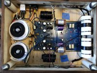
The wires from the transformer, goes to the center of the tag strip on the left where the hot and neutral wires go. It is connected to a second tag strip via the short green wire. Had to use two tags because I ran out of room. The ground from the iec goes to the second smaller tag strip, which is where the PCB ground cable is connected, as well as the three metal plates - they are connected via the black wires.
Just reread this.It's autotype, he meant "rotated".
This probably won't help, but for my first build I used a Khozmo stereo ladder for the master volume. The trick I learned was to snip the bridge between the input/output grounds, in other words, not connect them together.
Trying to understand where this should be snipped?
Ground loop mania!
Try this. One point and one point only. Not daisy connections. And make sure it’s a dedicated chassis ground point. It’s for your safety. Your primary wires from your transformers need to go on another tag strip, separately. In other words, the responsibIlity of a chassis ground is isolated, it’s only role is chassis ground. Not mounting a pcb or component. Just…chassis….ground.
See below:

In the above example: the purple wire is a shield wire coming from an Antek toroid. The black heatshrinked wire is a parallel set of wires which are individual ground wires coming from two amp pcb’s. And the green wire is a dedicated wire going from chassis ground to the IEC ground terminal. Notice how all the wires converge on ONE point.
Best,
Anand.
Try this. One point and one point only. Not daisy connections. And make sure it’s a dedicated chassis ground point. It’s for your safety. Your primary wires from your transformers need to go on another tag strip, separately. In other words, the responsibIlity of a chassis ground is isolated, it’s only role is chassis ground. Not mounting a pcb or component. Just…chassis….ground.
See below:
In the above example: the purple wire is a shield wire coming from an Antek toroid. The black heatshrinked wire is a parallel set of wires which are individual ground wires coming from two amp pcb’s. And the green wire is a dedicated wire going from chassis ground to the IEC ground terminal. Notice how all the wires converge on ONE point.
Best,
Anand.
Yeah, it’s maddening…Ground loop mania!
Try this. One point and one point only. Not daisy connections. And make sure it’s a dedicated chassis ground point. It’s for your safety. Your primary wires from your transformers need to go on another tag strip, separately. In other words, the responsibIlity of a chassis ground is isolated, it’s only role is chassis ground. Not mounting a pcb or component. Just…chassis….ground.
See below:
View attachment 1289548
In the above example: the purple wire is a shield wire coming from an Antek toroid. The black heatshrinked wire is a parallel set of wires which are individual ground wires coming from two amp pcb’s. And the green wire is a dedicated wire going from chassis ground to the IEC ground terminal. Notice how all the wires converge on ONE point.
Best,
Anand.
Forgive my confusion.
This would be so much more straightforward if I had an all metal chassis.
If I am understanding this correctly, you are saying that I need to have all the wires (earth ground/transformer ground/PCB ground/front panel ground) converge to a point that is directly connected to the metal top plate?
It appears he has chassis ground attached to his IEC screw terminal which yes is ONE point, but it’s a horrible idea. The safety of a chassis ground is lost as soon as the IEC screw gets loose (in shipping, or servicing, etc…). And I don’t see any connection between his IEC ground to chassis. Only directly to the PCB ground. And then the primary wires and neutral wires are also attached to that terminal strip. No bueno in my book. You can accidentally get shorting of the primary 120V to ground if not sufficiently insulated.
In any case, I think one of your issues is you have too many ground loop wires and a non contiguous metal chassis plate. It needs to be organized into one spot. Do some reading on star grounds in general and you’ll get a good idea afterwards.
Best,
Anand.
In any case, I think one of your issues is you have too many ground loop wires and a non contiguous metal chassis plate. It needs to be organized into one spot. Do some reading on star grounds in general and you’ll get a good idea afterwards.
Best,
Anand.
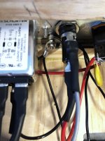
Made a ground point on rear panel. Drilled a hole and using a screw to anchor down the ground wires. Not using the enclosure of the IEC to ground the rear panel.
Top panel, rear panel, are connected to ground point - making a virtual metal chassis…
Transformer grounds and PCB grounds are connected to IEC ground.
Removed the metal straps that were holding the ps caps in place, replaced them with zip ties.
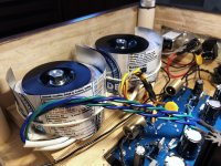
Elevated the transformers by 3/8” with a wood disc - trying to move them further away from the PCB.
And then, made a make shift shield for the transformers. Though I would do a quick test with this before I co copper shopping.
I


- Home
- Amplifiers
- Tubes / Valves
- Tubes4HiFi SP14 really noisy!
