
Francois, so true.The discussion started at around post #441 when I concluded the resistances of the Primary Windings power transformer’s (PT) secondary windings were too low to use with an unprotected 5AR4, and suggested a 100 Ohm resistor in each lead between the transformer and 5AR4 anode. You agreed.
@6A3sUMMER, starting in post #456, suggested that a “shared” 50 Ohm resistor between the PT center tap and ground would be equivalent. I was persuaded and I thought you were too, at least tacitly. Think it over and we could discuss further. But I believe it will work fine and not wreak havoc with anything.
@calpe had a combined resistance of 122 ohm available that he tried in the center tap lead and liked the results. His build proceeded from there with the somewhat lower than specified B+ of 315v DC, but I believe he preferred the slightly lower power and dissipation, with the added safety and tube life, compared to maximizing power and reducing tube life.
I am now faced with a couple of choices.
2x 100R 3W between secondary windings and the 5AR4's, and then check the B+.
I would of course then need to check where i would be able to fit safely two 3W resistors.
Or
Leave the 122R (two resistors in parallel giving me 122R) but increase their wattage.
The two resistors are already mounted, so it would be a matter of just increasing their wattage.
Yes, i have 316v but as you say i'm not going to hammer the EL's.
Cheers for this 6A3sUMMER, but this is over my head......Francois G,
As you know, the dissipation of the 122 Ohm resistor is very complex.
Look at it this way, the dissipation is the integral of V-squared/R; R= 122 Ohms
Set the scope for Cycle RMS, and then square the voltage measurement value, and divide by 122 Ohms.
If the scope can not "decide" what is a cycle, then set the scope time to show several alternations, and set the measurement to full time scale RMS.
You will get at least two different answers, under the following conditions:
1. Quiescent dissipation, and Class A push pull dissipation are relatively the same. (so is single ended class A)
2. Large signal Class AB push pull dissipation is greater.
Have fun measuring!
Hi Stonegreen,@calpe
Please measure the voltage across resistors R113, R117, R213 and R217 (all 100 ohms):
Do the resistors R112, R116, R212 and R216 still have the value of 300 ohms?
Thanks
Yes, R112, 116, 212 and 216 are 300 ohms.
Post #538 are the voltages you mention: -
B+ = 316v
Cathode V102 = 10.86v
Cathode V101 = 10.64v
Cathode V202 = 10.67v
Cathode V201 = 10.95v
R113/V101 pin 9 = 312.5v
R117/V102 pin 9 = 312.7v
R213/V202 pin 9 = 312.4v
R217/V201 pin 9 = 312.5v
I would like to try V102 with V201 and V101 with V202Cathode V102 = 10.86v
Cathode V101 = 10.64v
Cathode V202 = 10.67v
Cathode V201 = 10.95v
Your composite resistor may already be of adequate power dissipation. I forgot the wattage of resistors you used to make up the 122 Ohms, but I think you used a 5 watt and a 3 watt resistor. Could you tell us what you used, please. Measure the voltage across the combined resistor and calculate the dissipation through each resistor and compare. (Calculations as in post #521)Leave the 122R (two resistors in parallel giving me 122R) but increase their wattage.
The two resistors are already mounted, so it would be a matter of just increasing their wattage.
😕😕....i'm confused...I would like to try V102 with V201 and V101 with V202
Swap V101 with V201, i.e. use V102 / V201 in one channel and V101 / V202 in the other....i'm confused...
Here are the values for the total power of the tubes...
... for the current flow (Ohm's law)
V102 => 10.86 / 300 = 0.0362 A
V101 => 10.64 / 300 = 0.0355 A
V202 => 10.67 / 300 = 0.0356 A
V201 => 10.95 / 300 = 0.0365 A
... and for power dissipation
V102 => (316 - 10.86) * 0.0362 = 11.05 W
V101 => (316 - 10.64) * 0.0355 = 10.84 W
V202 => (316 - 10.67) * 0.0356 = 10.87 W
V201 => (316 - 10.95) * 0.0365 = 11.13 W
In order to calculate the power for g2, the voltages at the 100 ohm resistors are required, measured at the two connections.
Thanks Stonegreen for the calculations.Here are the values for the total power of the tubes...
... for the current flow (Ohm's law)
V102 => 10.86 / 300 = 0.0362 A
V101 => 10.64 / 300 = 0.0355 A
V202 => 10.67 / 300 = 0.0356 A
V201 => 10.95 / 300 = 0.0365 A
... and for power dissipation
V102 => (316 - 10.86) * 0.0362 = 11.05 W
V101 => (316 - 10.64) * 0.0355 = 10.84 W
V202 => (316 - 10.67) * 0.0356 = 10.87 W
V201 => (316 - 10.95) * 0.0365 = 11.13 W
In order to calculate the power for g2, the voltages at the 100 ohm resistors are required, measured at the two connections.
Am i within the power dissipation for my Sovtek EL84's?
For the EL84, g2 voltages on pin 9's these are as just measured: -
V102 - 10.75v
V101 - 10.53v
V202 - 10.50v
V201 - 10.93v
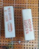
As for thoughts of getting higher wattage resistors to replace the resistors i've fitted from C.T. to ground (1x 150R + 1x 560R = 122R), i'll probably go for R.S. Components, chassis mount 10W, I can get them within a few days, unless there might be other thoughts?
Last edited:
Measured across the 122R, 25.8VACYour composite resistor may already be of adequate power dissipation. I forgot the wattage of resistors you used to make up the 122 Ohms, but I think you used a 5 watt and a 3 watt resistor. Could you tell us what you used, please. Measure the voltage across the combined resistor and calculate the dissipation through each resistor and compare. (Calculations as in post #521)
The Sovtek EL84 has a max plate dissipation of 14 W (Pa).Am i within the power dissipation for my Sovtek EL84's?
You haven't reached that level yet.
Attachments
Last edited:
25.8 * 25.8 / 122 ≈ 5.5WMeasured across the 122R, 25.8VAC
(1.2W at 560 ohms and 4.4W at 150 ohms)
Thank you yet again Francois. I think i'm going to play safe maybe something like https://uk.rs-online.com/web/cps/Your composite resistor may already be of adequate power dissipation. I forgot the wattage of resistors you used to make up the 122 Ohms, but I think you used a 5 watt and a 3 watt resistor. Could you tell us what you used, please. Measure the voltage across the combined resistor and calculate the dissipation through each resistor and compare. (Calculations as in post #521)
Chassis mounted resistors is a better solution, the heat being dissipated easier and i would probably do away with the fan too.
Thank you so much stonegreen, for the calculations, wattage not higher than 11.15 W, looking good i think and seeing your post 553 my Sovtek are rated at 14 W.Here are the values for the total power of the tubes...
... for the current flow (Ohm's law)
V102 => 10.86 / 300 = 0.0362 A
V101 => 10.64 / 300 = 0.0355 A
V202 => 10.67 / 300 = 0.0356 A
V201 => 10.95 / 300 = 0.0365 A
... and for power dissipation
V102 => (316 - 10.86) * 0.0362 = 11.05 W
V101 => (316 - 10.64) * 0.0355 = 10.84 W
V202 => (316 - 10.67) * 0.0356 = 10.87 W
V201 => (316 - 10.95) * 0.0365 = 11.13 W
In order to calculate the power for g2, the voltages at the 100 ohm resistors are required, measured at the two connections.
As for the damn R1 =122R you have kindly calculated the wattage at 5.5W, so choosing the chassis mounted types at 10W will solve all the problems.
Last edited:
Just another thanks to you all, your help has been second to none!
If we all lived closer to each, the drinks would be on me for the night!
If we all lived closer to each, the drinks would be on me for the night!
Glad you got to this point. You persevered! Congratulations!Thank you so much stonegreen, for the calculations, wattage not higher than 11.15 W, looking good i think and seeing your post 553 my Sovtek are rated at 14 W.
As for the damn R1 =122R you have kindly calculated the wattage at 5.5W, so choosing the chassis mounted types at 10W will solve all the problems.
If you are happy with this operating point (which is fine) go ahead with the 10 w resistor. If it were me I would go for a 100 Ohm resistor (10w) to raise the B+ just a few volts to about 320 Vdc.
I'll be making an R.S. order for the 10W's.
Francois, i remember from earlier checks using these resistor values (quite old resistors, 5% tolerances are probably past their best) i recall measuring: -
144R = B+ 315v - Cathode's = 11v
135R = B+ 319v - Cathode's = 11.18v
122R = B+ 323v - Cathode's = 11.33v
The same resistors giving me 122R, from the first checks, has just now given me a B+ of 315v
As we know from the parallel calculation a 150R + 560R should give 120R, which would be the ideal value.
I would probably prefer having two parallel resistors, let's see.....
Last edited:
- Home
- Amplifiers
- Tubes / Valves
- Tubelab SPP first timer build