
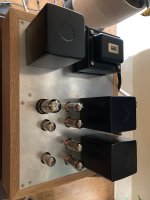
I'm having power supply problems and put it aside for the holidays but in the next few days this will appear on the shelf:

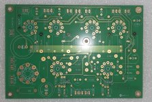
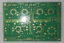
Hello Folks! I am wiring the SPP board and I have a couple of quick questions:
-the feedback connection from the 16ohm tap of the OPT, not the speaker 8 ohm tap, right? Its not specified on the schematic that is floating around.
-my power trans has 3x 6.3V 2.5A secondaries but the SPP takes a single 4A 6.3V, can I parallel the secondaries and feed it in like that? The secondaries should be very evenly matched in voltage.
thanks!
I've used the 8 ohm connection for feedback. You should be able to parallel the 6.3 volt windings. Just make sure thy are all IN phase. If they are colour coded (say three green and three black) you should be good. If not and you have three pairs of three different colours, will need to determine the polarity with your DMM. Not hard to do. Let us know if you need help.
S.
S.
Thanks Steve. The winding phases are labeled, so no problems there.
WRT the feedback, pretty much every schematic I found always use the full secondary for the feedback. I don't have a way to measure thd and imd but I wonder if someone has done that and has some insight on what diff, if any are present.
WRT the feedback, pretty much every schematic I found always use the full secondary for the feedback. I don't have a way to measure thd and imd but I wonder if someone has done that and has some insight on what diff, if any are present.
I used the 8 ohm tap because the trannies used on my SPP didn't have a 16. The SPP doesn't seem to have a lot of FB, at least compared to a Leak Stereo 20 I rebuilt. Try it on 8 or 16, use the one you prefer. I have seen schematics where the FB wasn't taken from the highest impedance tap. Good luck with your build.
S.
S.
If your global negative feedback sample comes from the same tap that your loudspeaker is connected to . . .
Generally, that will give the the global negative feedback signal the best corrections, because it includes your loudspeaker's impedance variations.
How can you properly change the tap where the global negative feedback comes from?
Example:
Your amplifier's global negative feedback comes from the 16 Ohm tap. But you are connecting your 8 Ohm loudspeaker to the 8 Ohm tap.
You would like to change the global negative feedback from the 16 Ohm tap, to the 8 Ohm tap.
Suppose the connection to the 16 Ohm tap, has a negative feedback resistor of 3k Ohms in parallel with a compensation cap of 100pF.
Because the voltage from the 16 Ohm tap is approximately 1.4 times the voltage from the 8 Ohm tap, you re-calculate the 3k Ohm and 100pF.
You need the resistance and the capacitance to keep the same feedback voltage to the input stage negative feedback node.
3k / 1.4 = 2142 Ohms, use a 2200 Ohm resistor. 100pF x 1.4 = 140pF, use the closest available capacitor value.
I picked the 3K Ohm and 100pF as an example, your original resistor and original capacitor may be different, but the concept of dividing the resistance by 1.4, and multiplying the capacitance by 1.4, is the way to calculate the new parts values.
Oh . . . suppose you are using a 4 Ohm loudspeaker on the 4 Ohm tap, and the original global negative feedback comes from the 16 Ohm tap.
Then divide the feedback resistor by 2, and multiply the compensation cap by 2, and connect them to the 4 Ohm tap.
This is a good set of resistance and capacitance to start with, because it keeps the same amount of global negative feedback, example 20dB before the modification, and 20 dB after the modification.
Caution:
If your amplifier is already marginally stable (almost unstable), this principle may not work.
Instead, you may have to do some testing with a square wave signal and an oscilloscope to properly adjust the feedback resistor and compensation cap.
If you do not have a square wave signal, and do not have an oscilloscope, and you simply move the original feedback resistor and compensation cap from the 16 Ohm tap, to:
8 Ohm tap, you get 3 dB less global negative feedback (such as was 20dB, now 17 dB),
or,
4 Ohm tap, you get 6 dB less global negative feedback (such as was 20dB, now 14 dB).
Generally this should work well, depending on how stable the amplifier was before the modification, and depending on how large the loudspeaker impedance versus frequency is, and what the loudspeakers phase angles are versus frequency.
One factor that has a large influence on how well this technique of using 1.4 factor or 2.0 factor, is the quality of the output transformer,
Specifically the Ratio of Leakage Inductance to the tap rated impedance.
Example: If the leakage inductance of the 16 Ohm tap is X, then if the leakage reactance of the 8 Ohm tap is X / 1.4, that is good, and the same goes for the leakage inductance of the 4 Ohm tap is X / 2.
Have Fun!
Last edited:
Thanks 6A3! My only choice is to assume that the SPP feedback is calculated for the 8ohm speaker's tap. I will re-check some documentation just in case. I am minutes from putting in tubes and firing this up, wish me luck! 🤣
i like to err on the side of caution and NOT connect the FB on first power up. Play some music through the amp, just touch the FB wire from the board to the OPT secondary, which ever one you choose. The volume should drop a bit, If it does you are good to go, at least as far as polarity is concerned. If it increases or you get howling feedback you will need to reverse the OPT primary connections to the board.
The first time you power up a newly constructed amplifier, and listen to it, is one of the most fun moments!
You will not forget it.
You will not forget it.
Well, things did not go super😢, one channel seems to work, the other starts to buzz as soon as the voltage gets over 300V (I connected some crap driver I have around).
Reading Steve's reply I have some suspicions that it is the feedback instability. I have 100pF cap in the feedback. I will take NFB that out after the break here. I measured a couple of things in between the two channels and everything checks out thus far. B+ is 331VDC with the two channel operational, I have to measure the bias current.
Reading Steve's reply I have some suspicions that it is the feedback instability. I have 100pF cap in the feedback. I will take NFB that out after the break here. I measured a couple of things in between the two channels and everything checks out thus far. B+ is 331VDC with the two channel operational, I have to measure the bias current.
Yes, disconnect the FB from the OPTs. Put shorting plugs in the input. Measure voltages at identical points in both channels and compare. Check all of your solder joints., reflow any that look vaguely suspicious . Make sure you have connected the OPTs primaries to the correct terminals.
No joy, yet. The one channel starts to 'motor boat' at 300v B+ as I raise the voltage with variac. It happens with or without NFB onnected.
I checked all resistors and found no mistakes in the PCB the output tubes are biased correctly 33ma 330v B+. So the B+ works, the output tubes work. it produces sound. I ohmed out the OPT everything seems fine. I have swapped the input tube on the affected channel: nothing. I could swap the OPT but the dcr are the same so I don't see the value. I need to swap the output tubes just in case.
I checked all resistors and found no mistakes in the PCB the output tubes are biased correctly 33ma 330v B+. So the B+ works, the output tubes work. it produces sound. I ohmed out the OPT everything seems fine. I have swapped the input tube on the affected channel: nothing. I could swap the OPT but the dcr are the same so I don't see the value. I need to swap the output tubes just in case.
It is quite easy to switch around the connections to the OPT from the connectors on the board. Sending a picture could help to check that.
I will check again but I have the feeling this is going to be a weird problem. There is nothing connected wrong that I can find, unfortunately. The 8k primaries have matching ~250 ohm dcr. Hard to get that wrong.
Nothing. Rechecked everything all resistors values, soldering joints, reconnected everything, replaced output tubes, the one channel is still motorboating above a certain voltage. It is making sound on both channels before that and one channel is quiet.
Will try swapping OPT but I am out of ideas.
Will try swapping OPT but I am out of ideas.
Unbelievable! Found the problem! So embarassing. I had the feedback and the ground wiring swapped on one channel. 👎The labeling on the PCB is consistent throughout except for the o1 o2 swap on the last terminal block. I guess George wanted to make sure diyers are really paying attention and I wasn't ! 😎
Anyways, the amp is now playing and sounds fantastic. I just have a few songs in but the full body and mid bass, the imaging is wonderful. I think it may edge out my SE 300b on rock and likes to play loud. I think the PS noise is a touch higher than on the 300b with the ears to the horn but nothing to worry about. BTW I used 6П14П-ER from Kazakhstan and philips 12AT7 from our friendly ebay neighbor in MS. Wow this thing is silky smooth!
Anyways, the amp is now playing and sounds fantastic. I just have a few songs in but the full body and mid bass, the imaging is wonderful. I think it may edge out my SE 300b on rock and likes to play loud. I think the PS noise is a touch higher than on the 300b with the ears to the horn but nothing to worry about. BTW I used 6П14П-ER from Kazakhstan and philips 12AT7 from our friendly ebay neighbor in MS. Wow this thing is silky smooth!
- Home
- Amplifiers
- Tubes / Valves
- Tubelab SPP first timer build