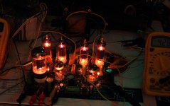
Thanks Russ, now this is interesting, the metal plate mounting disc is getting hotter than the tranny, and possibly this plate is what is heating up the tranny. Is it possible, since I rewound both the 6.3V and 5V windings, that if I wound them in opposite directions it could heat up the steel mounting disc? Each winding covers half the core, they are not on top of each other. I will hold the tranny in there with a wooden mount and see what happens. I can think of no other explanation, how can the mounting disk get hotter than the transformer itself, it should be the other way around...
Is it possible, since I rewound both the 6.3V and 5V windings, that if I wound them in opposite directions it could heat up the steel mounting disc?
Each winding covers half the core, they are not on top of each other. I will hold the tranny in there with a wooden mount and see what happens.
I can think of no other explanation, how can the mounting disk get hotter than the transformer itself, it should be the other way around...
The metal plate might "feel" hotter to touch, than the plastic insulation, even tho it might not be
Anyway, I have experienced pretty strange changes of induction when winding a toroid for speaker crossover
Orientation of the different windings matters a lot
I dont know, but you could try to reverse the low voltage connections to your trafo
And remember to isolate your trafo from box and top metal plate with rubber
It usually comes with all toroids
Personally I like to use even thicker rubber pieces, so that the toroid is "lifted", and the heat can escape as well
And it can be an effective way to isolate mechanical trafo vibration/buzzing, but the screw needs to be adjusted with just the exact right tightening
Thanks Russ, now this is interesting, the metal plate mounting disc is getting hotter than the tranny, and possibly this plate is what is heating up the tranny. Is it possible, since I rewound both the 6.3V and 5V windings, that if I wound them in opposite directions it could heat up the steel mounting disc? Each winding covers half the core, they are not on top of each other. I will hold the tranny in there with a wooden mount and see what happens. I can think of no other explanation, how can the mounting disk get hotter than the transformer itself, it should be the other way around...
By any chance do you have a complete conductive current path through the mounting bolt and returned through the chassis? If so, you may be exciting a significant AC current in this loop just as if you had an extra single-turn winding around the toroid, and the heat you are getting is the resistive loss in this current path.
Just a wild guess.
tinitus, I think you are right about the metal plate feeling hotter than the plastic insulation, I had a good feel of the windings and indeed they get hot too.
torrence, I have a wooden chassis, so no shorted turn, but have read warnings about that.
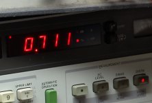
I checked the windings and yes the 2nd rewound heater winding was in a different direction to the other heater winding, which was not rewound but only shortened to reduce 6.3V to 5V. I rewound the 2nd winding again but no change in temp, so that's one question answered... I remembered I have a thermocouple, took some measurements:
Time/temp C/temp F
9:00/25/77 - switch amp on.
10:00/48/117
11:00/59/136
12:00/64/146
1:00/69/155
2:00/72/160
3:00/73/162
4:00/73/162
I emailed Antek to ask what is the max operating temp of this tranny. Its probably OK but I'm surprised it gets this hot with no bottom cover on the amp and plenty of ventilation.
I came across this post in another forum:
"It is worth to note that any commercial toroidal transformer can be accurately taylored to the correct voltage ratio by manually wiring additional windings in series with the secondary. If the wiring is winded in the same direction of the secondary the winding voltage is additive, the opposite is true in the other case."
This means a 6.3V winding could be changed to 5V simply by winding a few turns in the reverse direction...in my case just 5 turns of say 16 or 18 gauge wire. Ahhh, that would be too easy...
torrence, I have a wooden chassis, so no shorted turn, but have read warnings about that.
I checked the windings and yes the 2nd rewound heater winding was in a different direction to the other heater winding, which was not rewound but only shortened to reduce 6.3V to 5V. I rewound the 2nd winding again but no change in temp, so that's one question answered... I remembered I have a thermocouple, took some measurements:
Time/temp C/temp F
9:00/25/77 - switch amp on.
10:00/48/117
11:00/59/136
12:00/64/146
1:00/69/155
2:00/72/160
3:00/73/162
4:00/73/162
I emailed Antek to ask what is the max operating temp of this tranny. Its probably OK but I'm surprised it gets this hot with no bottom cover on the amp and plenty of ventilation.
I came across this post in another forum:
"It is worth to note that any commercial toroidal transformer can be accurately taylored to the correct voltage ratio by manually wiring additional windings in series with the secondary. If the wiring is winded in the same direction of the secondary the winding voltage is additive, the opposite is true in the other case."
This means a 6.3V winding could be changed to 5V simply by winding a few turns in the reverse direction...in my case just 5 turns of say 16 or 18 gauge wire. Ahhh, that would be too easy...
Any news on the testing front? It's been quiet on the boards about the Simple PP lately. I need my fix, lol.
Just a few notes.
With GFB connected it sounded a little bit lifeless so I disconnected it, and increasing the screen grid resistors to 820 ohms gave a really nice sound (less distortion).
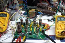
I stumbled upon some red 5mm Fairchild MV50152 LED's, they are rated at 100mA continuous. I thought 6 in series might make a nice cathode load for the output tubes, but pushing the limits of the LED's perhaps. I did some tests and it seems they will handle 160mA continuous for several minutes, and still function as they did before, and the variation in voltage with current is minimal. So I very carefully matched four sets of 6 to give identical forward voltage at the expected running current, and made up four LED arrays and fitted them into the PCB. Please excuse the rough cutout for the cap, I got injured and sanding it out would have been more painful than what is was worth. It will get cleaned up in due course. I have around 320V-330V B+ (depending on mains voltage), the plate current was approx 34mA after fitting the LED's, and after about 15 hours its crept up to around 38mA. I'm not sure if these MV50152's will do the distance yet, will keep my eye on them.
The sound has excellent detail with the LED's, and they give a deeper bottom end and higher top end frequencies. Originally I left the 1000uF cathode bypass caps in place, then took them out, then put them back in again. Jury is still out on that one.
I am very happy with this amp. Thanks again George.
SigloOne, did you end up getting a PCB, or maybe waiting until George gives the official go-ahead?
Ian.
With GFB connected it sounded a little bit lifeless so I disconnected it, and increasing the screen grid resistors to 820 ohms gave a really nice sound (less distortion).
I stumbled upon some red 5mm Fairchild MV50152 LED's, they are rated at 100mA continuous. I thought 6 in series might make a nice cathode load for the output tubes, but pushing the limits of the LED's perhaps. I did some tests and it seems they will handle 160mA continuous for several minutes, and still function as they did before, and the variation in voltage with current is minimal. So I very carefully matched four sets of 6 to give identical forward voltage at the expected running current, and made up four LED arrays and fitted them into the PCB. Please excuse the rough cutout for the cap, I got injured and sanding it out would have been more painful than what is was worth. It will get cleaned up in due course. I have around 320V-330V B+ (depending on mains voltage), the plate current was approx 34mA after fitting the LED's, and after about 15 hours its crept up to around 38mA. I'm not sure if these MV50152's will do the distance yet, will keep my eye on them.
The sound has excellent detail with the LED's, and they give a deeper bottom end and higher top end frequencies. Originally I left the 1000uF cathode bypass caps in place, then took them out, then put them back in again. Jury is still out on that one.
I am very happy with this amp. Thanks again George.
SigloOne, did you end up getting a PCB, or maybe waiting until George gives the official go-ahead?
Ian.
George certainly fulfilled the design criteria with something that is easy to build, requires no adjustments and sounds good straight out of the box. The only reason I'm playing with it is to learn what different things sound like (newbyitis). I put LED's in a 6P1P PP and they gave similar characteristics. It's not easy to get them to bias correctly, takes a lot of time in homework, testing and matching. In the RLD the screen voltages are regulated to set the bias. In the 6P1P amp I ended up fitting mosfet source followers to drive the output tubes and trimpots to adjust the bias, worked out well. Another interesting and much simpler mod would be to try fixed bias, I would like to compare that to using LED's. There is definitely an extended frequency range with the LED's, where does it come from? And will fixed bias also give this characteristic? One way to find out...do it.
I have thought about buying another PCB and do a "drop in" Simple Baby Huey, just to see what it sounds like. The Simple PP PCB would require some substantial modifications for that, but it would be a lot easier/cheaper/faster than building a whole new amp. An RLD would be easy with this board. The RLD uses a seperate B+ for the small signal tubes and would require some small support PCB's but I think easily doable. No mods to the board required, plus you get the option of a tube rectifier.
I have thought about buying another PCB and do a "drop in" Simple Baby Huey, just to see what it sounds like. The Simple PP PCB would require some substantial modifications for that, but it would be a lot easier/cheaper/faster than building a whole new amp. An RLD would be easy with this board. The RLD uses a seperate B+ for the small signal tubes and would require some small support PCB's but I think easily doable. No mods to the board required, plus you get the option of a tube rectifier.
Ian444, I am waiting for the official go ahead from George. My current plan is to put two Simple PP's into one chassis using 6CW5's. The main question is what to use for a PT. George had received a couple of Antek toroids he was going to try, but he's been busy, so I wait.
You are waiting to hear if the 2T230 gives too much B+ for the 6CW5? It sounds like it will work, but you may need to do a trick to lower the screen voltage. I don't have any 6CW5s, so I can't try it. If you are up to some "fun" and have the patience, you could unwind part of the secondary and reduce the voltage that way if it turns out to be too much (nice thing about toroids). Otherwise you could just get two 1T200s.
rkinze, yes that is basically where I am at. I am not sure how to unwind a toroid. I've never done anything like that before. Willing to take advice though.
There are a few threads of people doing it with the low voltage windings. I'm not sure how the HV secondaries are wound. If they are like the 6.3V secondaries, then they are wound in parallel at the same time (more likely). If they are wound one over the other, then it's probably not that feasible. Maybe someone who has been inside one of these can comment. I haven't...yet.
Basically, you unwind the clear plastic film tape on the outside, remove the two 6.3V secondaries (just a dozen or so winds of heavy gauge copper) and set them aside. Then unwind another layer of plastic film and now you have access to the HV secondaries. You'll need to unwind and remove 30V worth of turns (or you could unwind 15V worth and rewind it back on in the opposite direction). How many turns to remove? Count how many turns they used for the 6.3V winding and multiply that by about 4.75.
Basically, you unwind the clear plastic film tape on the outside, remove the two 6.3V secondaries (just a dozen or so winds of heavy gauge copper) and set them aside. Then unwind another layer of plastic film and now you have access to the HV secondaries. You'll need to unwind and remove 30V worth of turns (or you could unwind 15V worth and rewind it back on in the opposite direction). How many turns to remove? Count how many turns they used for the 6.3V winding and multiply that by about 4.75.
Any news on the testing front? It's been quiet on the boards about the Simple PP lately....George had received a couple of Antek toroids he was going to try, but he's been busy, so I wait.
Yeah, the audio stars are definitely not aligned right now. There are two forces at work here.
About three weeks ago Sherri received some bad news, her moms cancer has now spread to her lungs. She has beaten the odds so far, but this is far more serious. It looks (pending more tests) like she will enter the hospital in about two weeks for one more experiment. This requires both of them to live in a Pittsburgh hospital room for 4 to 6 weeks. I plan to visit for about a week in mid May (to coincide with the Dayton hamfest). Sherri and I have been spending as much time together as possible doing stupid stuff that doesn't ordinarilly get done while she is here.
I work in an electronics plant where people get laid off every few weeks. I have worked there for over 37 years, again beating the odds. When I was approached about being the lead engineer on a year long development program, I knew what I was getting into, but I could not refuse. Yes, this means I'm stuck at work until late most nights. As deadlines get closer it will get worse.
My boss went home early with the flu today, so I left early to work on my Simple P-P. This is the first time I have worked on it in about 4 weeks.
Ian444, I am waiting for the official go ahead from George. My current plan is to put two Simple PP's into one chassis using 6CW5's. The main question is what to use for a PT.
Are you planning to run them in PPP for a stereo amp? I am working on a dual Simple P-P amp using EL84's. I have seen it run for a total of 2 or 3 hours, but it is the next amp being built. I have not tried to parallel the channels with 6CW5's yet, and it will be a while before I get to it. This will require a 1500 ohm OPT (I don't have one). If you are planning 4 seperate channels with 2 boards the issue is just the power transformer.
George had received a couple of Antek toroids he was going to try
I have a couple of 1T200's and one of them resides in my 6CW5 amp. It works just fine but I only get about 15 WPC. Therefore, I got a 2T230 and decided to try for more power. I can sat that just hooking it up to the board and flipping the switch in place of the 1T200 on a previously working amp resulted in glowing tubes. I have not had the time to research this any further. My amp was built before I got the 2T230 but I had planned to install it later. The dimensions for the 2T230 on the web site are WRONG and it will not fit into my amp.
I have sold about 10 boards so far. A few of those have been completed, with good results. Two boards, parts kits, and OPT sets were provided to beta builders. Both of those boards were built and tested as working amplifiers, but I don't think that either was made into a completed amp.
I had stated that some possible changes to the parts list might be forthcomming. So far the only change would be increasing the value of R3 from 10 K ohms to 30 K ohms. This raises the bias on the heater winding for better H-K voltages over all the possible voltages seen in this design. Another issue was raised but I do not believe a change is warranted yet.
Russ (rknize) reported seing some distortion at the grids of the output tubes using a scope as the amp is pushed into clipping. This was dependent on the type and condition of the 12AT7 that was used. At first I could not duplicate this issue, but Russ sent me the offending tubes. He suggested raising the value of the grid stopper resistors. This is a common defense against this type of distortion seen as the output tube grids are driven positive. With the 1K ohm resistors installed in the board (as per the existing parts list) some assymmetry in the drive voltage can be seen as the amp is driven to clipping. This is caused by the drop in input impedance of the output tubes grids upsetting the balance of the phase splitter. Some notching or crossover distortion can be seen at the amp output at this level. Increasing the grid stoppers to 10K ohms made the scope traces at the driver plates look better, but the overall amp distortion increased.
These effects were observed using sine wave testing at the edge of clipping. This should not have an adverse effect on music at reasonable levels unless you like to crank it into clipping a lot. Just to be sure I cranked some techno to the point where the bass was starting to distort and tried a few different grid stopper resistors. Resistors that are too big have a definite adverse effect on transient behavior. I liked the amp best with out any stopper resistors at all, but this may prove to be unstable on some tubes.
Siglo One, send me a PM or an email with the details of what you are planning, and what parts you already have. It make me a few days to answer though. Tubelab email is forbidden at work.
I would say my SPP is about 75%. I have yet to add a volume pot, a bottom plate and binding posts. I just have wires running from the board to my source and speakers. Otherwise it is pretty much good to go. One thing I have learned now is that if I don't get the chassis done before I fire up the amplifier it is going to take a LONG time to finish it as it is too easy just to flip the switch and enjoy the amp. I really like this amplifier. It definitely has a different sound compared to my SSE. I just picked up a Lafayette 250a amplifier that is a PP 6cw5 design and if I cannot sell it I might salvage the iron and the tubes and try the opts in the simple pp.
Now if I can scrap together the funds and salvage some parts to keep costs down I would really like to build a Tubelab SE to complete the Tubelab Trio.
Now if I can scrap together the funds and salvage some parts to keep costs down I would really like to build a Tubelab SE to complete the Tubelab Trio.
Last edited:
Hey George,
There were two issues I was seeing. One was the weird "nipple" distortion effect that looks funny but is probably not that serious since the output tube in question is already in cutoff. It looks better with bigger stoppers, but I didn't compare distortion spectra between them.
The main reason I sent the tubes was because I noticed a lot of asymmetry even at low input levels with them...especially those two used JJ and the two brand-new EH tubes. Did you notice this? When I put a meter across the grid and cathode of the splitter at idle, I always saw a nearly zero or even slightly positive Vgk. That explained why it had no headroom on the upswing and gave the amp higher 2nd order distortion even at 1W output. Increasing R106/206 addressed that for these tubes and gave the splitter the headroom it needed.
OK, it finally rained today. In fact it was rather nasty outside all day, so I got to experiment with the Simple P-P.
I compared your tubes against a randomly selected pair of old GE's that were on my bench in the amp that I have been working on. This amp has been modded a bit, but ALL of the components in it are as per the published parts list. The mods are in the output section and intended to increase the power just a bit. Both channels in this board are wired in parallel through a single OPT, so this is a PPP setup. I first tested the amp at 10 watts with my GE tubes. The total distortion was 0.46%. I tried several combinations of your tubes to find that the worst in this amp are the EH tubes. With these installed the distortion at 10 watts is 0.97%. The scope traces for the grid drive on one output tube and the speaker output trace overlay perfectly after adjusting the gain on one channel.
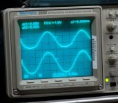
So I cranked the drive up until I could see some obvious distortion on the drive going into an output tube. The first photo shows the obvious assymmetry on the top trace. The amp was making 3.4% THD at 58 watts output at during this photo.
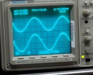
Next without changing anything, I simply replaced the EH tubes with the GE's and made the same measurement. The second photo shows no assymmetry. The amp is still making 58 watts, but the THD is now 1.1%. Clearly something is not right with the EH tubes, but the numbers would have appeared acceptable, until you tried the GE's.
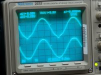
THe third photo shows the nipple effect. Here I cranked the drive up until the nipple appeared. The power output is now 60 watts and the THD is 1.8%. The amp is entering clipping.
The main reason I sent the tubes was because I noticed a lot of asymmetry even at low input levels with them...especially those two used JJ and the two brand-new EH tubes. Did you notice this?
I compared your tubes against a randomly selected pair of old GE's that were on my bench in the amp that I have been working on. This amp has been modded a bit, but ALL of the components in it are as per the published parts list. The mods are in the output section and intended to increase the power just a bit. Both channels in this board are wired in parallel through a single OPT, so this is a PPP setup. I first tested the amp at 10 watts with my GE tubes. The total distortion was 0.46%. I tried several combinations of your tubes to find that the worst in this amp are the EH tubes. With these installed the distortion at 10 watts is 0.97%. The scope traces for the grid drive on one output tube and the speaker output trace overlay perfectly after adjusting the gain on one channel.
So I cranked the drive up until I could see some obvious distortion on the drive going into an output tube. The first photo shows the obvious assymmetry on the top trace. The amp was making 3.4% THD at 58 watts output at during this photo.
Next without changing anything, I simply replaced the EH tubes with the GE's and made the same measurement. The second photo shows no assymmetry. The amp is still making 58 watts, but the THD is now 1.1%. Clearly something is not right with the EH tubes, but the numbers would have appeared acceptable, until you tried the GE's.
THe third photo shows the nipple effect. Here I cranked the drive up until the nipple appeared. The power output is now 60 watts and the THD is 1.8%. The amp is entering clipping.
Attachments
Now squeezing 60+ watts out of a quad of JJ EL84's isn't normal, but nothing is glowing except heaters so I measured the power lost in the circuit. The plate voltage is 425 volts and the total plate current is 260 mA. This means that 110 watts is going into the plate circuit, and 60 watts are comming out, so 50 watts is dissipated in 4 tubes. 12.5 Watts is OK for a EL84.
Attachments
It's good to know that I am not completely insane. 😉
The trigger seems to be a cold biasing input section. There is not enough drop across the plate load to properly bias the phase splitter. The JJ tubes are (unexpectedly) worn, as I mentioned in my other thread and they test in my tube tester that way. However the EH tubes are not only new but also test strong in the tube tester. So they have good transconductance but bias cold in DC. The Chinese tube I sent you isn't that great either, but it is better than the EH tubes.
The trigger seems to be a cold biasing input section. There is not enough drop across the plate load to properly bias the phase splitter. The JJ tubes are (unexpectedly) worn, as I mentioned in my other thread and they test in my tube tester that way. However the EH tubes are not only new but also test strong in the tube tester. So they have good transconductance but bias cold in DC. The Chinese tube I sent you isn't that great either, but it is better than the EH tubes.
......Clearly something is not right with the EH tubes........
Can you hear the distortion with the EH tubes that the scope shows?
- Home
- More Vendors...
- Tubelab
- Tubelab Simple P-P