Has anyone tried removing the MOSFETs in the Tubelab SE? If so, how did it sound afterward?
I'm thinking of trying it to see if it puts out more of the tube "sweetness."
I'm thinking of trying it to see if it puts out more of the tube "sweetness."
I think you haven't gotten any responses because, for most people, including myself, the powerdrive circuit is what sets the TSE apart from more conventional amps. This is well documented on the Tubelab site.
Removing the mosfets presents some problems - the very real possibility of damaging the pcb in the process, and then all the experimentation required to reconfigure for their loss. You might be in a better position than most to try this, as your mosfets are already off board.
I think your question might be better phrased as: "Has anyone tried grafting a Tubelab front end unto a conventional DHT final?" because that's pretty much what you have after the powerdrive is removed. Presumably Tubelab has already done that and rejected it, as evidenced by the existence of the TSE.
I thought some about this while I was mowing today, and here's a pic of my proposal to graft a Tubelab front end on a conventional DHT final, thus implementing what is probably not that good an idea to start with.
I only see a couple of reasons to pursue this: I could use a utility amplifier for some purposes around the shack, maybe at the office. I have all the parts I need on hand, so long as we are talking a mono block.
I have an abundance of five and eight pin sockets, but only one four pin on hand, so I'm thinking of going with a five pin for the power tube socket, and use the four pin for the rectifier. Then I could use 46 or 47 and play around with DH pentode or ultra linear, thus potentially adding to my knowledge base in the process to make the project less like tilting at windmills.
Or, I could use the four pin for a 45 or 2A3, and use a conventional octal rectifier.
I'm thinking the front end to graft on would be the SSE front end, mostly because I don't want to fight with making a 5842 stable. I've got a seven pin socket shown, so the tube would be a 6AB4 (12AT7 equiv) or 6C4 (12AU7 equiv). Or a nine pin could be mounted, and just use half the tube, thus making it easier to move to a 5842 in the future. Cathode bias for the final. I think my 2.5 volt tranny has the suds to do DC if I want to go that way.
No guarantees this might happen. Just thinking. Lots of other stuff I need to do worse. Looks like it is feasible at no cost other than time.
Comments and criticisms welcomed.
Win W5JAG
Attachments

Last edited:
I'm thinking of trying it to see if it puts out more of the tube "sweetness."
Jeff,
If your output transformers have 3k or 3.5k secondaries (in addition to the 5k you are running at IIRC), try it out. Your 2nd harmonic should go up, giving it a warmer, "tubey" sound.
Thanks for the thoughts, w5jag. I meant no disrespect to George's design in asking about removing the MOSFETs. The idea isn't to "improve" upon it, but rather to see how the sound can be changed by making modifications.
The reason I asked about it is that I've been studying more 300B circuits and have noticed that they tend either to have (1) no CCS chips or transistors (i.e. the stuff published in Sound Practices during the early 1990s), (2) a traditional circuit topology but with a constant current source, or (3) a hybrid design (like the TSE) that uses ICs judiciously for providing consistent voltage and current regulation or ideal loads.
I'm curious to hear and learn about all of them, so I figured that the TSE could (temporarily) serve as an example of type (2) if it were possible to remove the MOSFETs and make minor adjustments to run it safely.
I'm planning to build a pair of classic 6SN7-->300B mono blocks anyway -- either the J.C. Morrison 300B SET from the Fi Primer or the JE Labs one -- not because of something lacking in the TSE but because I want to explore what can be done with the 300B. I like the sweet-sounding "romance" of those older designs, and it would be nice to have that to listen to as well as the refinement and power of the TSE.
Since the TSE was my first amp build, I can't really comment on your proposed grafting of a Tubelab front end onto a DHT final. But I don't see why it wouldn't work well given that George's gain stages are so stable. If you're less knowledgeable about DH pentodes, then maybe a Tubelab front --> DHT build would be a more logical first step. Proceed to the more familiar unknown and then, when that has been tackled, go for the pentode version.
Also, FWIW, my MOSFETs are still on-board; it's the 300B heater regulators that are now off-board, as I use one per channel.
zman01: My OPTs have 5K primaries and 8ohm secondaries. I was thinking of using them to breadboard a classic 300B circuit as described above but not sure if the 5K primary would eliminate too much of the 2nd order harmonics I'm looking for. I'd love a pair of 3K MagneQuest FS-030 or 3.5K Lundahl 1623 but won't have the budget for something like that for quite some time to come.
Last edited:
There's no real harm in trying. Pluck R14 and R25 (20 kΩ, 3 W) off the board. They're easy to de-solder. Then short the MOS from gate to source (pin 1 to pin 3). You can to that with a short piece of wire soldered to the pins directly. Just be careful that you don't short to the drain (middle pin) by accident as that will let the smoke out of your components for sure.
Do note that the bias voltage for the output tube will decrease by about 5 V when you short out the MOSFET, hence, the bias current for the output tube increase rather dramatically. Thus, I strongly suggest turning the bias pot to the minimum bias current setting before making the modification. Readjust the bias to the desired bias point after the modification. Do the same when you revert back to the original SE circuit.
I performed this experiment during the development of my DG300B. When driven hard, the blocking distortion that George describes on the PowerDrive page was clearly visible on the o'scope connected at the amp output. The speakers made some rather rude noises and the woofer cones moved quite violently until the amp recovered.
If you want more tube sweetness, I suggest using a cathode follower rather than a source follower. It's the same circuit topology, just a tube instead of the MOS transistor. E88CC makes a good cathode follower. Just be careful not to exceed the Vgk, Vak, and Vbk specs of the tube. I use a cathode follower in my DG300B.
Tom
Last edited:
.... There's no real harm in trying. Pluck R14 and R25 (20 kΩ, 3 W) off the board. They're easy to de-solder. Then short the MOS from gate to source (pin 1 to pin 3).
Tom
Tom, if you had posted that about eight hours earlier, I probably would have tried it last night. Wife and child were out of town, so I spent the evening stripping a dumpster dive Eico HF 32 down for iron and parts. I'm supposed to be reworking a closet, so if I skip another night, bloodshed ( mine ) might be involved.
...I'm planning to build a pair of classic 6SN7-->300B mono blocks anyway -- either the J.C. Morrison 300B SET from the Fi Primer or the JE Labs one -- not because of something lacking in the TSE but because I want to explore what can be done with the 300B. ....
Jeff, if you are getting into building, you need to put the Claremore hamfest ( usually February or March ) on your to do list - lots of good tubes and parts to be found there. A couple of years ago I dragged home a sackful of micanol base 6SN7's and 6SL7's for a buck per. Also, Joplin which is usually in August. Again, lots of good tubes and parts to be found. WBOSND was there last year selling tubes.
Jeff's question has really got me interested in making a simple hybrid DH utility amp, though.
Crazy question: I intend for the amp to be mono, but I see stereo inputs as being a useful feature, since almost everything, including some dual band radios, has stereo output these days. Here's the crazy question: use the SSE front end with one half of the 12AT7 ( or 12AU7 ) taking each channel, then apply one channel to one grid of a 46, and the other channel to the second grid of a 46.
Will I get a normal mono output mixed from both channels? Try it and see what happpens?
Win W5JAG
Thanks for the idea, Jeff! Let the experimenting begin.
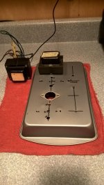
I cut the left side of the "chassis" in about an hour and a half last night. I'm not really a fan of cake pan construction - the metal is flimsy and harder to work with than a real chassis, imo. About all it has going for it is that it is cheap, and Wal Mart has a decent selection. Instead of a punch, I used a nibbler and file for the tube socket. I was afraid a punch would leave the flimsy metal so wavy I'd never be able to beat it back out.
I cut the chassis to accept either transformer pictured. Both are about 250-0-250, but the smaller one lacks a 5 volt secondary. The bigger iron could be useful for bigger tubes, and I want the ability to accomodate those with minimal hassle.
I haven't cut the right side yet - other than the location for the electrolytic cap, I'm undecided about the type of rectifier tube ( or solid state ) and the front end tube type.
Power junk will go on the rear, line in and speaker out on the front.
I'll make a new thread once it gets closer to fruition so as not to further pollute Jeff's thread.
Win W5JAG
Attachments
Well, given your initial trepidation, Win, I didn't expect you to try something like this, so I feel amused, impressed, and guilty all at the same time!
I will definitely follow your build thread with interest. And thank you so much for the tips on the hamfests, which sound really exciting. Claremore is really close by, and I'll try to find other ones too.
tomchr: thanks for the suggestion on how to do it. Given the chassis and layout I have right now, I don't think I could short the MOSFETs and add another pair of tubes as cathode followers. But I'll keep thinking on this.
The TSE is so good at what it does, that I'm thinking I'll leave it as-is (except for some minor capacitor tweaks) and just do new point-to-point builds. I might do an SSE as point-to-point monoblocks, since I like monoblocks and love the idea of a utility amp for tube rolling and UL/feedback/rectification experimentation, or a headphone amp, or a Morrison 300B with 3K Transcendar OPTs (they seem to be still in business), or a 300B/2A3 amp with Magnequest 2.5K OPTs and switching for heater voltages, or, or, or...
... Joplin hamfest in August, eh?
Last edited:
Well, given your initial trepidation, Win, I didn't expect you to try something like this, ....
WTH, since the little bit I know comes from making mistakes, why not rig up an inexpensive flexible test mule, make a few more, and learn something? Maybe something useful or interesting will come from it.
With a hand selected 12AT7, the SSE front end should have no trouble swinging enough volts to easily drive a 45 at 45 B+ voltages, so I'm not sure I'm even going to fool with it. Still undecided. The 46 and 47 are much less popular, so I'll probably start with those.
I'm fairly far along on it, btw, the tube rectifier ( 6X5 ) power supply is installed and putting out all the filament voltages, and unfiltered B+ DC.
Win W5JAG
Along the way to coming up with the PowerDrive and the TSE, I built a 45 based amp without mosfets. At low volumes the sound was pretty similar to a mosfet enhanced TSE. The mosfet or a good cathode follower (high Gm pentode) allows the 45 to be driven closer, and into the positive grid region without distortion or blocking. Given that the 45 is only good for 1.5 to 2 watts, most systems see this region far more often than you realize unless you have really efficient speakers (97db+).
The 45 is actually rated for A2 or AB2 operation and a good pair will produce about 20 watts in AB2 push pull.
Although not specified, the 300B responds to A2 and AB2 P-P, but doesn't provide much more power. I can get 10 watts in A2 SE and 30 watts in AB2 P-P.
Most of the "tubeyness" found in a SE amp, and especially a DHT SE amp, comes from the higher levels of 2nd harmonic without the higher order harmonics being too high. This comes from the interplay between the driver tube, output tube, OPT and speaker system. In any two stage amp some of the 2nd harmonic from the driver tube will be cancelled in the output tube since they both have slightly "bent" transfer curves but are operated out of phase with each other.
Removing the mosfets may (or may not) affect this since the dynamic load on the driver tube is no longer constant. The total amp gain will go down as a result of the increased load on the driver, and may not be sufficient if it is close now. Some CD players can not drive a 300B to clipping in some TSE's depending on OPT and speakers.
If you can find some 307A's go with the 5 pin socket, and leave options available for more B+. Triode wired they make great 300B's and will eat 400 volts.
I have been experimenting with a pentode driving a pentode wired 307A. It has promise, but that's all I want to say about it now.
The CCS loaded 12AT7 will drive a 45 to clipping. It won't drive a 300B to clipping from a CD player. There is not enough gain.
A CCS loaded mosfet buffered (PowerDrive) 12AX7 will work, and some 12AX7's are capable of remarkably low distortion numbers at fairly high output voltages in this manner.....some just roll over and distort.
The 45 is actually rated for A2 or AB2 operation and a good pair will produce about 20 watts in AB2 push pull.
Although not specified, the 300B responds to A2 and AB2 P-P, but doesn't provide much more power. I can get 10 watts in A2 SE and 30 watts in AB2 P-P.
Most of the "tubeyness" found in a SE amp, and especially a DHT SE amp, comes from the higher levels of 2nd harmonic without the higher order harmonics being too high. This comes from the interplay between the driver tube, output tube, OPT and speaker system. In any two stage amp some of the 2nd harmonic from the driver tube will be cancelled in the output tube since they both have slightly "bent" transfer curves but are operated out of phase with each other.
Removing the mosfets may (or may not) affect this since the dynamic load on the driver tube is no longer constant. The total amp gain will go down as a result of the increased load on the driver, and may not be sufficient if it is close now. Some CD players can not drive a 300B to clipping in some TSE's depending on OPT and speakers.
I'm thinking of going with a five pin for the power tube socket,
If you can find some 307A's go with the 5 pin socket, and leave options available for more B+. Triode wired they make great 300B's and will eat 400 volts.
I have been experimenting with a pentode driving a pentode wired 307A. It has promise, but that's all I want to say about it now.
The CCS loaded 12AT7 will drive a 45 to clipping. It won't drive a 300B to clipping from a CD player. There is not enough gain.
A CCS loaded mosfet buffered (PowerDrive) 12AX7 will work, and some 12AX7's are capable of remarkably low distortion numbers at fairly high output voltages in this manner.....some just roll over and distort.
You know, I had totally, I mean totally, forgotten about 307A.
I bought a half dozen Ken Rad's at Fair Radio the last time I went to Dayton.
Win W5JAG
I bought a half dozen Ken Rad's at Fair Radio the last time I went to Dayton.
Win W5JAG
The mosfet or a good cathode follower (high Gm pentode)
Yep. High gm is needed for a good cathode follower.
Some CD players can not drive a 300B to clipping in some TSE's depending on OPT and speakers.
... a problem which gets further compounded by the folks using their phones/tablets/laptops to drive amps. Many of the modern sources only provide about 900 mV RMS of output swing. Need a preamp with some stones...
Tom
I have the power supply and a power amplifier final stage running.
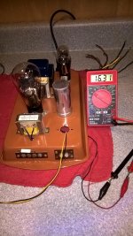
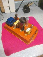
This is a test mule, so no effort at beauty is being made - the nasty looking hardware and input / output terminals are from a dumpster dive Eico HF-32, I stripped down a few weeks ago. The PT is a used hamfest scrounge; the other parts were NOS hamfest scrounge, with the exception of the OPT, which is an Ebay deal. I spent a couple of days slowly reforming the 60 year old Sprague filter cap. The spray paint was supposed to be orange, but twenty years in a hot garage apparently made it more brownish.
The power supply is conventional: 6X5 rectifier, choke input. Not much to say here.
The PA is a 46, for now; a 47 will come later. AC on the filaments, cathode bias; the cathode resistor and bypass are on the filament transformer CT. I had a spot of trouble here - my target was a cathode voltage of DC 16 volts, and on power up, I got 0.12 volts. After about ten minutes, it dawned on me that I had left out the grid resistor. I installed a 220K resistor since I will be using the Tubelab front end in some form.
I repowered it up, and, of course, it still didn't work. This took a bit more thought. The 46 is a dual grid tube. I assumed the two grids were more or less identical, and I wired them to each other, simulating a triode. For whatever reason, this didn't work. I backed up, and wired the grid nearest the plate, what I call the second grid, to the plate, and repowered the device.
This time, it worked - cathode voltage settled at 16, exactly as I had planned. Anode voltage was 194 volts, pretty close to what PSU predicted for a choke input. That's the first time I've had that happen, but this is the first time I've used measured data on all the parts in my power supply.
The bias resistor is 470 ohms, bypassed with a 100 uF cap ( because I had a bunch of them, and figured that was a reasonable starting point ). That's about 30 mils, and about 6 watts.
Dizzy with success, I jumpered a signal generator to the first grid input cap, fed it a 1 kHz tone, and got a clean, hum free, 1 kHz tone from a test speaker. For fun, I fed the output of the AA-1 into it - it could drive it to about 90 milliwatts, and showed two tone IMD at a bit less than 6%, as shown in the second pic.
The remaining hole in the "chassis" can take either a 7 or 9 pin socket, so I have some flexibility here. Once I've tweaked the final and have it working the way I want, I"ll graft an SSE front end unto it, as a start.
The odd second grid of 46 needs to be explored. The OPT will need to be changed to a UL type at some point. The existing one has taps at 5K and 7K ( I'm using the 7K tap ) so of course I'll try to use the 5K tap as a feedback element before I spring for a new OPT.
Win W5JAG
Attachments
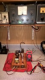
The mule has a functional front end now - essentially the SSE front end sans ( for now ) the CCS, and the cathode bypass cap is 1000 uF, because I didn't have a 1500 uF handy. In lieu of the CCS, a 10K resistor is the anode load. My plan is to put the CCS on a small perfboard, so it can be installed and removed as one component.
For now, I used a 7 pin front end socket, so the front end is either 6AB4 ( 12AT7) or 6C4 ( 12AU7 ). 6C4 and 6AB4 have similar enough pin out that it is possible to wire the socket to accept either tube.
Loaded B+ comes in at about 260 volts with a CLC power supply.
I've done some preliminary testing with both tubes, and 46 and 47 wired as triodes. My notebook is back at home, but this is what I recall:
Both tubes do about 850 mw output as triodes. 46 is running at ten watts, so is at about its limit, while 47 is at about eight watts and can ( and will be ) further exploited.
Both tubes can be easily driven to clipping with the 6AB4, taking about 0.5 to 0.7 volts RMS. It takes about 1.4 to 1.6 volts RMS to drive to clipping with the 6C4. The 47 drives easier than the 46. That could be problematic in some applications. Adding the CCS may change this, I don't know.
Two tone IMD for all combinations is pretty similar, about 8 to 9% at 100 mw output, and 4-5% at 50 mw output. Adding the CCS may change this, I don't know
This OPT is not good as a hi fi OPT, it's high frequency response is fine beyond 20kHz, but it is down 5 dB at 100Hz. This is probably why the amplifier is unexpectedly and completely free of residual AC hum. A better OPT is in order. It works fine as-is as a medium fi utility amplifier where response below 200Hz is not required. It has already put in a fair amount of time in that application.
Using the 5k tap as a quasi UL feed appears to have merit with the 46. Attaching the 5K tap to the second grid gave an immediate increase in power output to 1.45 watts at clipping, and an across the board two tone IMD reduction of 2-3% at all power levels. I don't know how it affects input sensitivity, if at all. I haven't tried 47 that way, yet.
Member hareynolds also did some work with 46 in UL and that thread is in this subforum.
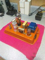
Pics are attached, still wired as triodes; there's not much to it really - very few components required to make a working amplifier. No leads were cut so the parts can be recycled for further use.
I'm already looking ahead to possibly a push pull amp using 45, 46, or 47 - I have enough tubes to do either. For some reason, almost all my 46 and 47 are globes, which is kinda cool. Not sure how that happened.
Win W5JAG
For now, I used a 7 pin front end socket, so the front end is either 6AB4 ( 12AT7) or 6C4 ( 12AU7 ). 6C4 and 6AB4 have similar enough pin out that it is possible to wire the socket to accept either tube.
Loaded B+ comes in at about 260 volts with a CLC power supply.
I've done some preliminary testing with both tubes, and 46 and 47 wired as triodes. My notebook is back at home, but this is what I recall:
Both tubes do about 850 mw output as triodes. 46 is running at ten watts, so is at about its limit, while 47 is at about eight watts and can ( and will be ) further exploited.
Both tubes can be easily driven to clipping with the 6AB4, taking about 0.5 to 0.7 volts RMS. It takes about 1.4 to 1.6 volts RMS to drive to clipping with the 6C4. The 47 drives easier than the 46. That could be problematic in some applications. Adding the CCS may change this, I don't know.
Two tone IMD for all combinations is pretty similar, about 8 to 9% at 100 mw output, and 4-5% at 50 mw output. Adding the CCS may change this, I don't know
This OPT is not good as a hi fi OPT, it's high frequency response is fine beyond 20kHz, but it is down 5 dB at 100Hz. This is probably why the amplifier is unexpectedly and completely free of residual AC hum. A better OPT is in order. It works fine as-is as a medium fi utility amplifier where response below 200Hz is not required. It has already put in a fair amount of time in that application.
Using the 5k tap as a quasi UL feed appears to have merit with the 46. Attaching the 5K tap to the second grid gave an immediate increase in power output to 1.45 watts at clipping, and an across the board two tone IMD reduction of 2-3% at all power levels. I don't know how it affects input sensitivity, if at all. I haven't tried 47 that way, yet.
Member hareynolds also did some work with 46 in UL and that thread is in this subforum.
Pics are attached, still wired as triodes; there's not much to it really - very few components required to make a working amplifier. No leads were cut so the parts can be recycled for further use.
I'm already looking ahead to possibly a push pull amp using 45, 46, or 47 - I have enough tubes to do either. For some reason, almost all my 46 and 47 are globes, which is kinda cool. Not sure how that happened.
Win W5JAG
Attachments
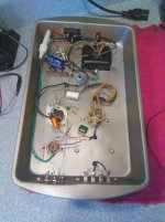
Great stuff, Win! Sorry I haven't had a chance to respond yet: we're in the middle of moving so I'm not as tuned in as usual. But this is fascinating. I know you said it's OK as a mid-fi utility amp, but can you describe the sound characteristics?
It looks really cool, btw. Love the orange.
It looks really cool, btw. Love the orange.
.... I know you said it's OK as a mid-fi utility amp, but can you describe the sound characteristics? ....
Jeff, I'm releuctant to, yet, for several reasons: first, the OPT is just to get it working - it's not intended to be hi fi, yet. Second, I actually haven't listened to it through anything but my test speaker, which may not even be mid fi.
I used it all weekend listening to field day and talk radio, and it worked well for that. I've also got some baseline numbers to build from.
I found that I have some more of this same transformer with the 5K and 7K secondaries, but about 50% larger, and they might have a better low frequency extension. I hope they do, because I'm starting to think that a quasi, or true, UL 46 could be a project with merit, and that would save me having to buy yet another set of SE OPT's.
I thought it was interesting that two tone IMD actually went down when the tube was moved from triode, to quasi UL. I didn't expect it to work at all with that OPT.
I'm also really intrigued with the idea of a very simple, very low cost, directly heated push pull amp, and I kind of think that this is one of the directions your thread will veer off into - a mosfet less simple quasi UL 46 SE, and a mosfet less simple PP quasi UL 46.
Get your 46's before the price skyrockets ....
Win W5JAG
Someone more knowledgeable help me out here, please:
If my arithmetic is correct, with the 8 ohm secondary, the 7K tap has a turns ratio of 29.5, and the 5K tap has a turns ratio of 25.
So, by using the 5K tap as a UL feedback point, is this a 16% tap? Or something else?
Win W5JAG
If my arithmetic is correct, with the 8 ohm secondary, the 7K tap has a turns ratio of 29.5, and the 5K tap has a turns ratio of 25.
So, by using the 5K tap as a UL feedback point, is this a 16% tap? Or something else?
Win W5JAG
I thought you take the square root of that number?
I'm at our weekend house for the holiday, and I actually have a hardback of Radiotron Designers Handbook 4 here, so, near four year old willing, I may try to read up on feedback and transformers.
Win W5JAG
I'm at our weekend house for the holiday, and I actually have a hardback of Radiotron Designers Handbook 4 here, so, near four year old willing, I may try to read up on feedback and transformers.
Win W5JAG
In the little time I had to look, I didn't see much in RDH. There is a whole chapter on feedback, which I didn't even have time to skim.
In the amplifier chapter, it describes partial triode operation at 570:
"... while triode operation is obtained when the screen is connected to the plate end of the primary. Any desired intermediate condition can be obtained by connecting the screen to a suitable tap on the primary. In such intermediate condition the valve operates as a pentode having negative feedback applied to the screen with a section of the load impedance common to both electrodes, and minimum high level distortion with push pull operation is usually obtained when the tapping point is about 20% of the total primary turns." (my emphasis added)
This just leaves me with more questions. The 5K tap as a feedback point would be at about the right point - if you start at the opposite end of the primary from the usual way it is done. Does this make any difference?
edit: have I made two dissimilar triodes in parallel by doing it this way?
It would seem not to in this instance, but the second grid in 46 isn't a screen; also, distortion went down from pure triode operation, instead of increasing, so maybe it is something different altogether. I don't have any regular UL OPT's free at the moment, for comparison. You can look straight down at the grids in a globe 46 - I don't recall the second grid showing signs of distress in this mode.
I guess I've lost sight of the mule's purpose - clearly, the SSE front end can drive these alternative flea power directly heated tubes to clipping, without the intervening mosfet follower.
Win W5JAG
Last edited:
- Status
- Not open for further replies.
- Home
- More Vendors...
- Tubelab
- Tubelab SE: Removing MOSFETs?