Hi,
At best that xformer with a full wave bridge and big cap PSU would give you a bi-polar supply of 30V.
In essence, to the tube that equates a 60V supply.
Cheers,😉
At best that xformer with a full wave bridge and big cap PSU would give you a bi-polar supply of 30V.
In essence, to the tube that equates a 60V supply.
Cheers,😉
Actually, that has given me a good idea!
As soon as I can I will establish a Gallery on:
"The Tube Gainclone for DIY Buffs" members.ozemail.com.au/~lisaras
Hi Joe, did you ever get that gallery up and running?
Nuuk said:
Hi Joe, did you ever get that gallery up and running?
Alas, the spirit is willing but the flesh is weak (mis-quoting JC).
I have been run of my feet lately, I have only a few weeks left (19 days I think) and much ado. My trek to the land of Euros takes precedence at this stage. Remind me when back 3rd week of December. May I pinch some things of your site? Did you know that in most countries Copyright is implied even if the Copyright Notice is not even shown. This is because electronic publishing has most of the rights that paper publishing has... interesting thought!
Joe R.
Alas, the spirit is willing but the flesh is weak (mis-quoting JC).
Yes, I know the feeling well!

May I pinch some things of your site?
Certainly - I owe you big time for the idea of the VBIGC!
Did you know that in most countries Copyright is implied even if the Copyright Notice is not even shown.
Yes, I did, that's why I always ask before including anything on DD.
OK folks, who has built a buffered chip amp and got some pictures to show us? I want to expand the Gainclone Gallery and Joe will also want a good selection when he has time to create his. Of course, I also feature non-buffered versions in the DD Gainclone gallery !
Joe, I hope that you are enjoying your time over our way! If you come to the UK, I will get PeterM over to Heathrow with the red carpet. 😉
Hello,
Thanks a lot for your tube hybrid invention! I am on my way to making one (collecting the parts list does take a while ... )
However, I have a couple of questions. Can I use a different supply voltages for the tube and the chip? (i am looking at around +/- 50V for the tube and +/- 35V for the chip). Is that going to cause any problems? And the original circuit presented on the diyAudio forum is slightly differently from the one on the webpage. There is a pre-out on one and not the other, and the number of tubes used looks different. Anyway, my main question is, do I need to "preamp" the input before feeding the tube hybrid or the tube will handle the preamping part?
Thanks a lot ...
Fishy said:However, I have a couple of questions. Can I use a different supply voltages for the tube and the chip? (i am looking at around +/- 50V for the tube and +/- 35V for the chip). Is that going to cause any problems? And the original circuit presented on the diyAudio forum is slightly differently from the one on the webpage. There is a pre-out on one and not the other, and the number of tubes used looks different. Anyway, my main question is, do I need to "preamp" the input before feeding the tube hybrid or the tube will handle the preamping part?
Yes, more voltage for the tube is OK, and many prefer it. If you take another gander at this thread, there is a more in depth discussion on this, and one successful builder does use a higher tube voltage.
On your latter questions, you are confusing the commercial JLTi with the design Joe publishes for DIY. The DIY design is 1 tube for 2 channels, has no preamp out, and takes a source input directly.
leadbelly said:
Yes, more voltage for the tube is OK, and many prefer it. If you take another gander at this thread, there is a more in depth discussion on this, and one successful builder does use a higher tube voltage.
On your latter questions, you are confusing the commercial JLTi with the design Joe publishes for DIY. The DIY design is 1 tube for 2 channels, has no preamp out, and takes a source input directly.
Agreed re the voltage, in the JLTi it's actually 55V, but in the simpler DIY version, is just as you correctly described. This lower voltage is easier to achieve as 25V AC secondary windings are easy to source, and they will get you 35V DC . So it was done for simplicity's sake, to make it a DIY project as accessible as possible, parts wise and also that this is an ideal way for DIY'ourselfers to get into their very first tube project, no high voltages but still tube.
Regards
Joe R.
PS: To Fishy (not you real name, right?), below you will find links to bo the the JLTi (not DIY but a completely finished project) and the DIY version, just in case you haven't seen these yet.
Joe Rasmussen said:
PS: To Fishy (not you real name, right?), below you will find links to bo the the JLTi (not DIY but a completely finished project) and the DIY version, just in case you haven't seen these yet.
Hello Joe ... Thanks a lot for your reply! I will check out the links and read thru this (longggg) thread 🙂
I have those voltage questions because I've bought a couple of surplus toroids that have secondary (ac) voltages of 38V. I am using one for +ve, and the other one for -ve. So I will end up with a 53-0-53 DC for the tube.
To make matters a little complicated, I will be using the same secondaries (from the two toroids) with switching voltage regulator circuits (to bring it down to around 40-0-40) to supply power to the LM3875s.
I have a remaining question though. On the website, it mentioned that the commercial version of the JLTi has unity gain preamp. In my mind, preamp always provides some gain (>1). Is that true? Since I will be taking the preamp-out from my receiver and feed that into the tube hybrid amp, I wanna make sure the amp is not "preamping" again ... or I might run into too big a signal for the chip input.
Thanks again ...
Horace
"To make matters a little complicated, I will be using the same secondaries (from the two toroids) with switching voltage regulator circuits (to bring it down to around 40-0-40) to supply power to the LM3875s."
Oh dear,
unless these swiching regulators are specifically designed for audio with much filtering on the o/p this could be seriously less than optimum.
even with filtering on the o/p chances are that the RF hash will find it's way back through into the ealier PSU stages and mess up the valve supply.
I would think good quality, low noise analogue regulators, would be a much better bet. I am not familier with these devices so cannot name numbers but I think Linear Technology make some quite good ones
mike
Fishy said:
I have those voltage questions because I've bought a couple of surplus toroids that have secondary (ac) voltages of 38V. I am using one for +ve, and the other one for -ve. So I will end up with a 53-0-53 DC for the tube.
To make matters a little complicated, I will be using the same secondaries (from the two toroids) with switching voltage regulator circuits (to bring it down to around 40-0-40) to supply power to the LM3875s.
I can foresee a bit of a problem here, the tube and filaments needs to be turned on before 3875 with some delay, allow filaments warm-up and tube stage to stablise. That is why the idea was to use a separate transformer for the tube front-end. If you turn on the whole together there will some rude noises coming out of your speakers.
I have a remaining question though. On the website, it mentioned that the commercial version of the JLTi has unity gain preamp. In my mind, preamp always provides some gain (>1). Is that true? Since I will be taking the preamp-out from my receiver and feed that into the tube hybrid amp, I wanna make sure the amp is not "preamping" again ... or I might run into too big a signal for the chip input.
To be pedantic, it does have gain, that it X1.
If you use my values for the 3875 inverted stage, this will give you plenty of gain, equal to that of a power amp and preamp combined, well, near enough. The reason for the tube stage is to act as a buffer that not only optimises the circuit (like keep feedback on the straight and narrow), but because it really does sound good, as evidenced by others. Put a pot on the input of the buffer and you have a variable gain power amp, or feed your CD or SACD Player directly into it (oh yeah, DVD too).
I don't have much experience with switching regulators, but by nature these devices are noisy (switching noise, unless generating a sine wave), I suspect with rising spectral characteristics. The delay required for the front-end makes for further complications still. A separate transformer is not an expensive proposition and it helps keeing things simple. Just keep its AC Mains permanently ON (by-pass AC switch), plug into power, wait 30 secs, turn power switch ON, which switches 3875 only.
Give it some thought.
Joe R.
Joe Rasmussen said:
I can foresee a bit of a problem here, the tube and filaments needs to be turned on before 3875 with some delay, allow filaments warm-up and tube stage to stablise. That is why the idea was to use a separate transformer for the tube front-end. If you turn on the whole together there will some rude noises coming out of your speakers.
Right ... thanks for your reminder, I almost forgot about this requirement. From the info I've gathered, I think I am better off using a separate transformer for the tube and the chip. However, if I were to stay put
and use just one supply for both, is it OK to put a switch on the DC supply side (i.e. after the bridge and caps) such that it will be a "no load" situation when the switch is open?hmm ... and ... is it OK to use toroid for the tube but a regular E-I transformer for the chip? I kinda think that theoretically I can, but has anyone tried that?
Horace
Fishy said:
... is it OK to put a switch on the DC supply side (i.e. after the bridge and caps) such that it will be a "no load" situation when the switch is open?
I do see a problem here as well. You would have to use a 2 pole switch and it needs to be highly, in fact perfectly, synced. If one side of the rails come on a fraction of a second before the other, you will have instant DC offset into your speakers during that period. The cone on your speakers will either pulse in or out. This not a problem when we switch a transformer on its primary side as it will all come alive together.
hmm ... and ... is it OK to use toroid for the tube but a regular E-I transformer for the chip? I kinda think that theoretically I can, but has anyone tried that?Horace
I use a toroidal on the tube. I-E transformers are still used in power amps. Unless you meet people who have a preference for one or the other, then that is all it is. It's just that toroidal are generally compact, not too expensive and have low external field that in some cases is good in keeping induced hum away. The down side is that toroidals are prone to very high turn-on peak current when the AC is high either on the positive or negative side of the waveform. You need a larger AC mains fuse than I-E, generally speaking. Others may have additional thoughts on this, but if you got a suitable I-E then by all means use it, assuming sufficient VA rating and hum shouldn't be a problem if sited with reasonable care.
Joe R.
hi Joe,
With regards to your tube buffered gainclone's power supply, I would like to enquire if it is alright to share the power from the same transformer windings, but different rectifier bridge.
I have a 200VA rated (but looks like a 300VA) trannie. Please help me check the schematic attached. I understand I will lose the tube B+ be on standby. Thanks!
Cheers!
Attachments
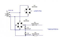
I would like to enquire if it is alright to share the power from the same transformer windings, but different rectifier bridge.
Joe will be midnight surfing by now 😉
You need a separate transformer for the valve buffer and the amp so that the valve buffer can be powered up approximately 30 seconds before the amp.
More on this at HERE .
Just a question about the output resistor (the 0.22Ohm) ... can I use a wirewound? or it's better be metal film as well?
Thanks!!
Thanks!!
Just a question about the output resistor (the 0.22Ohm) ... can I use a wirewound? or it's better be metal film as well?
A wirewound will do the job or you can pay a lot more for something more exotic. Go with the wirewound to get you up and running.
Thanks for the link. I cant seem to get to that site from the main page.Nuuk said:
Joe will be midnight surfing by now 😉
You need a separate transformer for the valve buffer and the amp so that the valve buffer can be powered up approximately 30 seconds before the amp.
More on this at HERE .

So does it mean that as long as I can delay the powering on of the LM3785 >30 seconds after the turn on of the tube HT I'm safe and can tap the rail from the same trannie? 🙂 Thanks!
BTW, I want to remove the volume control pot. How should I go about playing with the input resistor value? I'm aware that the 1n3 cap. is affected by the attenuator value, but don't have the time and resource to play around with different values. Thanks once again!
Cheers!
w00t said:
Thanks for the link. I cant seem to get to that site from the main page.
So does it mean that as long as I can delay the powering on of the LM3785 >30 seconds after the turn on of the tube HT I'm safe and can tap the rail from the same trannie? 🙂 Thanks!
BTW, I want to remove the volume control pot. How should I go about playing with the input resistor value? I'm aware that the 1n3 cap. is affected by the attenuator value, but don't have the time and resource to play around with different values. Thanks once again!
Cheers!
With a buffer you can use almost any value you like in place of the pot. I suggest 47K to 100K. The 1n3 (or 1n2 or whichever you end up with as it's worth experimenting with this value by ear) is not affected because the tube buffer isolates it.
Joe R.
Thanks for the link. I cant seem to get to that site from the main page.
Main page? You just click on the link on this page and it works. 😉
So does it mean that as long as I can delay the powering on of the LM3785 >30 seconds after the turn on of the tube HT I'm safe and can tap the rail from the same trannie? Thanks!
Well that's right BUT as Joe said, it would mena swirtching from the secondary side of the transformer and this is NOT recommended.
I hope you don't mind me saying but some of us spend a lot of time here answering questions like this on how to avoid buying a transformer. They really are not that expensive and if a design calls for two (or three) then it probably does so for good reason. 😉
Nuuk said:
I hope you don't mind me saying but some of us spend a lot of time here answering questions like this on how to avoid buying a transformer. They really are not that expensive and if a design calls for two (or three) then it probably does so for good reason. 😉
Thanks Nick, I couldn't have put it better myself.
Joe
- Status
- Not open for further replies.
- Home
- Amplifiers
- Chip Amps
- Tube with Power IC Output Stage - JLTi