retailer said:jmsegui
This the millivoltmeter with the precision rectifier it is tested and working; yours looks OK. I have drawn a circuit but not yet built a prototype of the true RMS millivoltmeter I will post the circuit if you want.
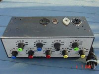
It is better to use 10 turn type trim pot for both they will be easier to set. I put C4 on the RAT tester board then shielded cable to the range switch. R7,R8,R9 mounted on the switch, and more shielded cable to the millivoltmeter board. If you use a moving coil meter for the output indicator you can leave out R10 150R, it is part of the feedback circuit and internal coil resistance of the meter is used instead. I used a LCD panel meter because it has much better resolution than moving coil meter, it is cheaper ($AU9.95) and there is no need to draw a scale for the meter face. As it is my circuit is set for 200mv fsd you may need to experiment with a series R with a moving coil meter. The down side to using a LCD panel meter is that it must have its own power supply, it cannot share a power supply with the same device that it is measuring (ie the millivoltmeter circuit). At first I thought to use a 9v battery, current comsumption is very low and the battery should last a long time, but in the end I settled for a separate regulated 9vdc supply for the LCD meter, no need to open up the tester to change the battery, also battery always seems to go flat when you need it the most. I'm attaching a pic of my tester, I wound my own mains transformer and only used common filament voltages 2.5, 5, 6.3 and 12.6. The two small transformers are for millivoltmeter and LCD panel meter. Millivoltmeter is at the right made on veroboard. Valve sockets are on top. The three meters are for valve current, anode volts and screen volts. Valve current meter is switchable to read 0-10 and 0-50 mA.
Reailer
I´d insert some mods (with your permission!) in the millivoltmeter circuit. C4, C5 and C6 across input resistors could provide some frecuency correction at AC input. C7 and C8 would block any dc current from TL072 and finally, the two zener D5 and D6 could save TL072 from shorts. Please, comment.
I´d like to be more consistent with my understading in matching power audio tubes on RAT. Supposse a pair 6L6 on RAT, Plate 250, Screen 250, Cathode 77mA( Plate72+5Screen), fix the Gm to same value and then read the Gred (Cathode) voltage? if voltage diference is below 5% are they matched?
Please, any info arriving from you is always welcomed¡
jmsegui@ya.com
Attachments
Hi...
pricey but looks complete especially when you add the PC+software. Probably the best option now that the Sofia is out of production.
http://www.amplitrex.com/at1000.html
cheers
paba
pricey but looks complete especially when you add the PC+software. Probably the best option now that the Sofia is out of production.
http://www.amplitrex.com/at1000.html
cheers
paba
jmsegui
I have seen capacitors such as C4,C5 and C6 used in audio millivoltmeters for frequency correction at the voltage divider and they certainly wouldn't hurt, but I assumed that as we are only interested in one frequency namely 1Khz that they are not needed, so I didn't bother. As for C7 and C8, it didn't even occur to me that there could be a DC offset at the output of the TL072. During the testing of the meter circuit I checked it (using a signal gen.) against my FLUKE 87 series IV in 10mV steps up to 200mV, I recall it was within 1% or 2% all the way up to 200mV, perhaps the DC offset trim control on the TL071 takes care it. The two zeners are probably a good safeguard in the event of a shorted valve, as my tester is at the moment, the anode voltage meter dips as I increase the valve current if the valve under test has an internal short. I've seen some good fireworks inside shorted valves but so far no damage to the op-amps. (hence the need to add a shorts function)
From reading Steve Bench's text about the tester, it seems the valve under test finds its own bias. I have put two sockets on the front one wired to the cathode and the other wired to the grid, I can plug a DMM into here and measure the grid bias voltage. I tried this with an EL84 and the cathode to grid voltage was around -7 volts which matches the data sheet. I used this idea to match a box of cheap Russian EL84's matching them for anode current, Gm and bias voltage. From a box of 20 I was able to get 5 pairs, each matching within 5% for all 3 parameters. Of the remaining ones I was able to make some pairs with anode current and Gm matching. These I would say are close but not matched like the other 5 pairs. I plan to add a LCD voltmeter for this function on the front panel of my next tester so there is no need plug a DMM in, also I have a preference for it to be self contained.
I have also added a octal socket on the top panel which has anode, screen,grid,cathode and filaments. An add-on box with switched sockets plugs into this so I can test any valve that fits the sockets. There is a switch for each valve pin, the switch can connect anode or screen or grid etc to the pin that it is connected to. Here is a picture.
Attachments
Just a few comments,
I have a 1944 Hickok which I treat as a museum piece and do not use (although its in full working condition)
Aside: It has "Baccus Marsh Repeater Station - 1944" printed on the case, This was one of the first repeater stations for the Australian Overland Telegraph System, so the unit has some interesting history.
I have a Taylor Model 45D which is incredibly easy to use and great for quick checks.
I have an AVO MKIII which is my reference tester.
The Taylor suffers from the fact that it does its gm measurement at some arbitrary, fairly low tube current and as a result it consistently gives low gm readings on power tubes. Retesting the same tubes with the AVO MKIII at rated current give true (higher) gm readings. This is something to watch on any tester - for Power Tubes you need to be able to set the Anode Current at which the gm test is performed.
The Hickok cost me AUS$300
The Taylor was "scabbed" out of a dumpster bin behind the Physics Building at the University of Adelaide and cost me AUS$40 for a set of photocopied manuals and about 5 hours to set it back to work.
The AVO cost me AUS$1000
Cheers,
Ian
gingertube
I agree with you about the anode current, even though there is a workaround mentioned in my Taylor 45C manual I still want to increase the anode current capacity of ther RAT tester to 100mA for testing power valves. I also have bunch of valve testers, a couple of Taylors, the models preceding yours a 45B and a 45C, 2 of Eico 666, 2 of Eico 625, Avo CT160, Avo MKII, Avo 2 panel, Sencore TC109 Mitey Mite, Mercury 1100c and an ancient Confidence tester. All came from EBAY purchased as 'not working' and so far I've repaired the following
Avo MKII : simple fix; all controls siezed through years of non use
Avo CT160: besides a few dry joints, some well meaning person had oiled the meter movement and also the hair springs causing eratic meter operation, failure to return consistently to zero etc. I was hesitant to work on the meter but in the end had a go, managed to unsolder the hair springs and remove the coil assembly from the magnet. Cleaned out the oil, reassembled and adjusted, works perfectly.
45B: dirty switch contacts and a few components out of tolerance.
Eico 666: leaky selenium rect. dry electros, out of tolerance resistors and a switch wired incorrectly apparently from new.
The biggest challenge when I get around to it is going to be the Confidence tester, this dates from about 1930 and is in quite poor condition. Inside are hand made switches, a hand painted meter face and a UX201.
Quality of these testers ranges from 'el-cheapo' Mercury 1100c to excellently engineered and built Avo's.
I also agree with your comments about the Taylor, one of the easiest and quickest testers I've used, but falls short in the anode current dept.
The RAT tester is even easier to use but falls short in a few places that I hope to address with the next build. Why even make a valve tester when I have all the others, it must be because I just like to make things.
Retailerretailer said:jmsegui
I have seen capacitors such as C4,C5 and C6 used in audio millivoltmeters for frequency correction at the voltage divider and they certainly wouldn't hurt, but I assumed that as we are only interested in one frequency namely 1Khz that they are not needed, so I didn't bother. As for C7 and C8, it didn't even occur to me that there could be a DC offset at the output of the TL072. During the testing of the meter circuit I checked it (using a signal gen.) against my FLUKE 87 series IV in 10mV steps up to 200mV, I recall it was within 1% or 2% all the way up to 200mV, perhaps the DC offset trim control on the TL071 takes care it. The two zeners are probably a good safeguard in the event of a shorted valve, as my tester is at the moment, the anode voltage meter dips as I increase the valve current if the valve under test has an internal short. I've seen some good fireworks inside shorted valves but so far no damage to the op-amps. (hence the need to add a shorts function)
From reading Steve Bench's text about the tester, it seems the valve under test finds its own bias. I have put two sockets on the front one wired to the cathode and the other wired to the grid, I can plug a DMM into here and measure the grid bias voltage. I tried this with an EL84 and the cathode to grid voltage was around -7 volts which matches the data sheet. I used this idea to match a box of cheap Russian EL84's matching them for anode current, Gm and bias voltage. From a box of 20 I was able to get 5 pairs, each matching within 5% for all 3 parameters. Of the remaining ones I was able to make some pairs with anode current and Gm matching. These I would say are close but not matched like the other 5 pairs. I plan to add a LCD voltmeter for this function on the front panel of my next tester so there is no need plug a DMM in, also I have a preference for it to be self contained.
I have also added a octal socket on the top panel which has anode, screen,grid,cathode and filaments. An add-on box with switched sockets plugs into this so I can test any valve that fits the sockets. There is a switch for each valve pin, the switch can connect anode or screen or grid etc to the pin that it is connected to. Here is a picture.
You are rigth, it makes no sense to grow up the original design with non necessary items. I encolse my pcb board in witch I put the rotatory switch. Because it was already eched I´ll put some jumpers to cancel that new items. I´ll test this precision voltmeter this weekend.
About matching tubes, I misundertud you when you said you put a couple of sockets. I was thinking in a couple of octal sockets to match tubes, no binding post! Now is clear.
Yes please, post the true RMS millivoltmeter circuit.
jmsegui@ya.com
Retailerretailer said:jmsegui
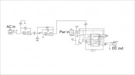
here is my true RMS millivoltmeter, input voltage divider is not shown as it is the same as other. You can dl data sheet for the chip from Analog Devices web site. I have not yet tested this circuit but don't envisage any problems.
Thanks a million!
jmsegui@ya.com
I got three testers 🙂
bought my first for $5 a simple emisiontester. External meter so its not that accurate, I dont use it anymore.
Then I got one AVO mk3 and one AVO mk1
these are quite nice to work with, I can test most tubes I got exept the realy big stuff
Have never accualy seen a Hickok or other model irl.
Got access to a AVO 163 to, its a good tester and I would like to have one 🙂
retailerretailer said:jmsegui
here is my true RMS millivoltmeter, input voltage divider is not shown as it is the same as other. You can dl data sheet for the chip from Analog Devices web site. I have not yet tested this circuit but don't envisage any problems.
I´ve found some component problems with the 7812/7912 to run the precision AC voltmeter beacuse I always got +12-14volts. Changed that components with simmilar results I´ve just decided to use LM317/LM337 regulators instead. I´ll check it today.
About 100mA RAT cathode current how did you get them? I´ve changed R16 down to 90ohm, R6 to 5ohm and R12 to10ohm but I have some dubs. Maybe I´d better change CR17 10volts zenet to a higher value...What do you think?
Regards a lot.
jmsegui@ya.com
Attachments
I haven't tried to get 100ma yet as I been tied up with building and moding gear for my son's recording studio. I was going to approach this way. Test the anode supply by shorting to earth thru a low value r and ma mater and see if is able to supply 100ma. According to the text on the tester it should be able to as it is the cathode supply that has been current limited. Cathode supply goes through r13 200ohms r16 133ohms and then the fet. I would try first r16 then r13, or maybe your transformer is too small and cannot deliver 100ma. If changing r16 and or r13 failed then it would time for more head scratching or possibly to email Mr. Bench and ask for advice. Sorry I can't be any more help at the moment, with my wife wanting the kitchen done and no.1 son wanting valve mics and preamps my stuff has had to wait. How has you mv meter turned out is it done yet ?
RAT Tube Tester - (Steve Bench) to test 5687
Hi Diyers,
I am interested in RAT tube tester and try to build one.
I have a the following tube want to test by RAT tube tester. Is it possible to test all the tubes? OR Adapter need? OR modified the circuit for the tube?
1) 5687
2) 6922
3) 6DJ8
4) 6SN7
5) 6SL7
6) 300B
7) 5U4
RAT tube tester is possible to test all the above tube except 5687.
How to modified to test 5687?
Best regards
Dominic
Hi, just wondering something - could someone please make some curve sheets for me if I mail them the tubes? I'm interested in implementing some 6AG7's in audio circuits but was curious about triode mode and 40% UL curves, which no one seemed to have... Other statistics like plate resistance, transconductance, etc. while in these modes might also be nice!
Thanks!
Thanks!
True RMS -- I have been experimenting with the LTC1966 and LTC1968 from Linear Technologies. They are more acurate than the AD536, 636 and 737 -- and less expensive as well. In fact, Linearity of the LT1966 is better than the data sheet indicates -- I get close to zero deviation from 100mV to 1V.
Only problem is that the LTC1966-8 devices are MSSOP so you don't hand solder them -- I use Kester solder paste and a dedicated toaster oven.
Here's a schematic of the AC Coupled LT1966 -- using an LT6203 low noise opamp as preamplifier and post-filter.
I found that the DC-Acurate post filter results in zero offset error.
Only problem is that the LTC1966-8 devices are MSSOP so you don't hand solder them -- I use Kester solder paste and a dedicated toaster oven.
Here's a schematic of the AC Coupled LT1966 -- using an LT6203 low noise opamp as preamplifier and post-filter.
An externally hosted image should be here but it was not working when we last tested it.
I found that the DC-Acurate post filter results in zero offset error.
An externally hosted image should be here but it was not working when we last tested it.
Something that would be very nice for doing a PC controlled curve tracer/tube tester would be a PCI card or USB device that could interface (multiple channels hopefully, and opto isolated) with the SPI (serial peripheral interface) used by a lot of D/A and A/D chips.
I have seen such a PCI-express card, but can't use that in my computer.
I have heard of using RS-232 serial port aux. control lines to make a software driven SPI channel, but this would be a little slow perhaps. But certainly low cost.
Next runner up would be some of the USB analog pods, but they all seem to have 8 A/D channels and 2 D/A channels and are somewhat expensive. I would like to find one with equal # D/A and A/D channels. Also the issue of isolation (galvanic, opto) from the PC comes up.
Besides curve tracer and tube tester functions, another function I would like to see or build would be a gain grapher. This would be for analyzing gain versus DC operating point for a single or double stage without a cap in the path of the DC part.
It would function by providing a SMALL fixed amplitude, 1KHz sine wave say, signal for input to the DUT summed with a swept (by software controlled D/A) DC offset. A 1 KHZ AC voltmeter (could be RMS or average) would then measure the AC output of the DUT and software would plot AC gain versus the swept DC level. This would provide a detailed picture of the non-linear behavior of the DUT providing no caps are in the DC path being measured.
A low cost - high performance approach to the gain grapher could use a soundcard. Here the sound card would be used to provide the small AC test signal and also to monitor the amplitude of the attenuated output AC signal. Software could control a D/A thru the parallel printer port or via an SPI/RS-232 port to generate the DC sweep signal which would be summed with the AC test signal by an Op. Amp. Would be a good way to do a tube gm test or Mu test also, and one could plot these parameters versus operating point. With a 24 bit sound card one could even plot linearity graphs for high N-FDBK circuits.
Don
See my post on Matt's analyzer. http://www.audioroot.net/index.html?analysis/mataa.html
If you only want to spend $30 or $40 you can get a USB interface from USB Micro -- it's my view that you can do a lot of the processing more elegantly on the DUT end with a dedicated DAC/ADC, rather than at the PC end.
Anyone who wants analog optical isolators should contact me by email as I have quite a few of the Siemens IL300 -- which are just like the HP (now Avago) HCNR-200's. Voltage to frequency converters are also an excellent way to interface high voltages to a PC.
Hi jackinnj,
The Matt's Analyzer looks quite interesting. Thanks for posting this. I have just quickly scanned thru the article so far. Appears that source code is provided and intended for programming one's specific tests. This looks like it could be set up to do an accurate phase measurement by autocorrelation between two sound card channels. (Something not often available)
I will have to look into the GNU Octave. (I have MathCad on my system so I suppose I could convert the source code to work on that. But since MathCad has gotten seriously harder to use as they keep making it easier to use...., I don't buy upgrades for it anymore.) I also have Visual Basic available with the RS-232 module and graphing modules snookered off the internet.
Looks like Matt's Analyzer only uses a soundcard for I/O and most soundcards don't support DC I/O which is needed to do the gain plot idea (DC op. point sweep). I suppose one could use another sound card channel to output a sine wave of some specified amplitude and an AC meter or equiv. circuit to derive a DC level from it. Not a great deal of accuracy needed for the DC level sweep anyway.
I have been using an RS-232 programmable power supply off Ebay, but these are hard to find, and mostly GPIB stuff around. Many projects will still want a DC capable A/D conv. channel though. The opto isolated RS-232 DMMs I have seen around are pretty slow and don't hand-shake for timing.
I will look into USBmicro. I have looked at Measurement Computing thus far, but no SPI interface stuff. I also just bought Jan Axelson's "USB Complete" book.
Don
You can use the LTC1966 to generate a very acurate DC level from a sine wave.smoking-amp said:Hi jackinnj,
The Matt's Analyzer looks quite interesting. Thanks for posting this. I have just quickly scanned thru the article so far. Appears that source code is provided and intended for programming one's specific tests. This looks like it could be set up to do an accurate phase measurement by autocorrelation between two sound card channels. (Something not often available)
I will have to look into the GNU Octave. (I have MathCad on my system so I suppose I could convert the source code to work on that. But since MathCad has gotten seriously harder to use as they keep making it easier to use...., I don't buy upgrades for it anymore.) I also have Visual Basic available with the RS-232 module and graphing modules snookered off the internet.
Looks like Matt's Analyzer only uses a soundcard for I/O and most soundcards don't support DC I/O which is needed to do the gain plot idea (DC op. point sweep). I suppose one could use another sound card channel to output a sine wave of some specified amplitude and an AC meter or equiv. circuit to derive a DC level from it. Not a great deal of accuracy needed for the DC level sweep anyway.
I have been using an RS-232 programmable power supply off Ebay, but these are hard to find, and mostly GPIB stuff around. Many projects will still want a DC capable A/D conv. channel though. The opto isolated RS-232 DMMs I have seen around are pretty slow and don't hand-shake for timing.
I will look into USBmicro. I have looked at Measurement Computing thus far, but no SPI interface stuff. I also just bought Jan Axelson's "USB Complete" book.
Don
I have a GPIB controllable power supply -- Tektronix PS5010 -- but I found that it was easier to roll my own with a DAC, opamp and some high power MOSFETs. Problem with the PS5010 is that you need the TM5006 mainframe which has a GPIB port.
- Status
- Not open for further replies.
- Home
- Design & Build
- Equipment & Tools
- Tube testers which is the best?