Post #90.
Keit is abusing the Forum Quote button, yet again, attributing -
"The only way to get it lower still is to use negative feedback or distortion cancellation."
to a member not even participating in the thread.
Obviously it is not intentional. What purpose could it serve? I's some sort of bug in the diyAudio software, not me.
I doubt that Merlimb will realy mind.
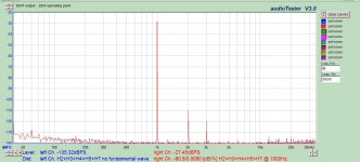
Yes, this is SN7 at preamp levels. And damn near perfect.
What's the voltage level and the load for that?
What rot!
I used a large swing to show that it isn't linear. If I used a short swing I'd need 5 decimal places, and the graphs don't have that level of precision.
If you are a smart guy, it should be obvious to you that if something is curved for large swings, its still curved for small swings.
This is standard technique to illustrate what is happeing. Nothing wrong with it.
You read into things what you want to read.
You merely showed that a purposely crippled stage is not linear. Nothing more - other than a suspicion that you are trying to avoid facing up to your rash claims.
Off the cuff, 2-3 V (would have to go back to get exact) feeding the grid of the next stage, which was a 46 triode-connected. At around 20V output the distortion was twice as high (which is still near perfect in my book). Most importantly only 2nd and 3rd; nothing else could be found. Differential stages throughout for full disclosure.
First they were "much the same", now it is more linear. I suggest you actually start to build some circuits and stop desperately trying to make your case from datasheets. It is not helping your trustworthiness.
The industry has always regarded the 12AU7 as a miniature 12SN7. The basic ratings are the same same mu, same Rp, etc
So If I check and then correct an erroneous view, that's a fault is it? Most people would regard it as a strength. Unlike certain other people who go to extroadinary lengths when shown wrong, and then resort to peronal attacks.
The beaut thing about datasheets is you dont need to trust me. You can get out the datasheets and check it yourself.
But posting measured spectrum plots does require trust. Especially if you don't describe how it was done, so somebody can replicate it.
Off the cuff, 2-3 V (would have to go back to get exact) feeding the grid of the next stage, which was a 46 triode-connected. At around 20V output the distortion was twice as high (which is still near perfect in my book). Most importantly only 2nd and 3rd; nothing else could be found. Differential stages throughout for full disclosure.
That's quite interesting. In my *SN7 measurements using a CCS load and Morgan's using a mu follower load, we saw roughly -55 to -60dB at 19.7VRMS, dominated by second. If we scale that by a factor of 10 to account for the difference in level, we would expect to see something like -75dB second. Now if I understand you correctly, you're looking at this differentially? That would largely null second, so we're down to third. I got about -90dB there (depending on the brand and the sample), so your data are pretty consistent with ours. 12AU7 is about 20 dB worse.
What was bias level and current for your measurement?
That does not make the two similar regarding distortion, which has been the debate. Had you measured, you would know.The industry has always regarded the 12AU7 as a miniature 12SN7. The basic ratings are the same same mu, same Rp, etc
Extraordinary lengths? You mean like posting actual real-world data, instead of making unsubstantiated claims from a data sheet? If you think real data is extraordinary, you are in the wrong forum.So If I check and then correct an erroneous view, that's a fault is it? Most people would regard it as a strength. Unlike certain other people who go to extroadinary lengths when shown wrong, and then resort to peronal attacks.
What you don't seem to grasp is that the data sheet is not the whole story; there is so much more to be understood about the differences between the SN7 and 12AU7. If you would build and measure you would understand. Perhaps you are content with 50% of the story, and applying it to 100% of the possibilities.The beaut thing about datasheets is you dont need to trust me. You can get out the datasheets and check it yourself.
If you would replicate it, I will post a video of my test setup and measurement in real time. But you won't replicate it, because you don't measure. So why bother with the challenge? Of course you would mistrust any data that would contradict your assertions, that doesn't surprise me.But posting measured spectrum plots does require trust. Especially if you don't describe how it was done, so somebody can replicate it.
If you would replicate it, I will post a video of my test setup and measurement in real time. But you won't replicate it, because you don't measure. So why bother with the challenge? Of course you would mistrust any data that would contradict your assertions, that doesn't surprise me.
There are other people who read these threads and actually do perform and post measurements. So throw us a bone, please. 😀
What was bias level and current for your measurement?
9 mA set by fixed CCS. Grid at -7V set by 390 shared cathode resistor, so plate voltage varies between 220V and 280V depending. Yes, this was a differential amp measured with a differential probe. My entire system is differential from DAC to speaker (until the speaker common gets grounded). Can provide a schematic if it helps. It has been posted in other threads already (Beyond the Ariel).
This was my output at 20V (differentially). And with flying leads all over the place; I suspect when the amp (now 85% built) is completed and dressed well, hum will be lower and perhaps slightly better performance.
I have over 120 12SN7, and each one was tested in a test jig. I have THD and individual harmonic data for each, if you are curious. Yes, some of us actually test. The SN7 lives up to the hype. Morgan was correct, smoked glass is the way to go.
Attachments
Last edited:

-140dB noise floor from a soundcard? Please tell us how it is done.
Small bins and an appropriate window function.
Will it? First, in real life where do you find two triodes which are very well matched across their entire curve? Second, are we talking about the 'unloaded SRPP' or the 'optimum loaded SRPP', as these rely on quite different distortion cancellation mechanisms. For the first case what signal current there is goes through both valves in the same direction; in the second case the signal currents are equal and opposite. In both cases the anode-cathode voltages of the two valves are going in opposite directions so you have to consider how ra/rp varies as a function of both current and voltage.Keit said:Yes, but active loading with another triode (SRPP) of the same type will give better than 1/10th the distortion of CCS loading
Let us take the naive view that the ra/rp of the two valves will exactly match, so the unloaded voltage at the anode will be undistorted (assuming constant mu). Add a load (there is always a load, otherwise we don't need the stage at all) and all you have done is halve the voltage gain and halve the anode impedance - so the non-linear anode impedance can still generate distortion into the non-infinite load. Typically, you have halved the distortion. Useful, but not game-changing. It gets more complicated when the optimum load is used, but people in audio rarely do that. In many cases the optimum load is much smaller than the output impedance so you get a much smaller voltage gain - OK for a simple power driver before SS was invented but less useful nowadays.
Misleadingly oversimplistic (to those with literal minds) would be a kinder verdict than "wrong".Keit said:DF96 said it in his post #49 of this thread. I showed that he was wrong and others decided to jump in.
Small bins and an appropriate window function.
I am not strongly versed in sampling theory, but that sounds about right. I use an M-Audio Profire 610. All balanced ins and outs. Additionally, at least with these specific measurements, you have a differential probe in the mix. As frustrating as the firewire interface has been, the front end measurement of this device has been stellar.
Would have to boot up the XP machine to get the specifics, but I typically set the sample rate at 96 kHz. FFT window of Blackman-Harris, 16k points, and number of samples either 16 or 32, depending on my patience level.
When the amp is fully built, I will likely start a new thread and begin some measurements. I would appreciate suggestions on how to best measure with the hardware I have.
Think of it this way- assume that the noise energy is evenly distributed with frequency. If the bin is narrower, there's less noise energy in it, proportional to the bin width. Bin width is set by sample rate (the lower the sample rate, the narrower the bin) and number of data points (the higher the number of data points, the narrower the bin).
bin width = sample rate/(2*number of points)
bin width = sample rate/(2*number of points)
And number of samples just behaves like the averaging function in the DSO, yes?
Drops the noise floor as spurious signals get averaged out instead of being displayed.
Drops the noise floor as spurious signals get averaged out instead of being displayed.
It's not so much that they're averaged out but that as the bin gets smaller, the energy in it is proportionally reduced. You have less water in a thimble than you do in a glass.
- Status
- Not open for further replies.
- Home
- Amplifiers
- Tubes / Valves
- tube regulators