Small bins help certainly, but I missed it earlier - the most important step is using a differential probe to null out the fundamental, so the measurement can be taken below the noise floor of the soundcard.
a differential probe to null out the fundamental
I missed that part- where was nulling mentioned?
Nope, no nulling. However, I do have one of Victor's oscillators, and made up my own notch filter, so that is certainly an option. But really, for measuring a power amplifier, I don't think this degree of accuracy will be needed. By the time I am measuring at the speaker output, I am sure there will be plenty of easily measured distortion well above the noise floor.
Cool. I see - a notch filter does the same thing, otherwise you cannot make measurements below the noise floor of the soundcard, that's what prompted my question on the -140dB noise floor.
Last edited:
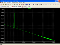
He didn't use a notch filter here and he's not measuring below the noise floor of the sound card. It's all about bin width.
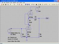
Here's another example, where I can personally attest that there was no notch filter or nulling:
http://www.diyaudio.com/forums/ever...fier-measurement-analysis-22.html#post2429720
Also see my measurement series in AX, where I present lots of other spectral plots with similar or even lower noise floors.
Then I must not understand the procedure, the M-Audio has a noise floor about -100dB, so how do you make a measurement down to -140dB without a notch filter or use a differential probe (or differential inputs)?
Ah, I see. You're confusing signal to noise with noise floor. Not the same thing. To get signal to noise over a bandwidth (and it is bandwidth dependent), you power-sum the noise voltages in each bin over that bandwidth and use that as the denominator. So the noise floor ends up considerably lower than s/n by definition. A differential measurement is irrelevant to that.
The industry has always regarded the 12AU7 as a miniature 12SN7. The basic ratings are the same same mu, same Rp, etc
The noval similar of 6SN7 is 6CG7/6FQ7, then the noval similar of 12SN7 would be 12FQ7.
My own suspicion is a bit more cynical. 😀
Your suspicion might be wrong in at least some cases. Certainly was my reason for going that route. 😀 There are certainly plenty of difficulties to be overcome. Mine hide in side of cans to prevent electro-static coupling to nearby chassis..
The noval similar of 6SN7 is 6CG7/6FQ7, then the noval similar of 12SN7 would be 12FQ7.
Yes!
Err.. They make these things called "twin triodes". Two identical triodes in the one glass envelope.... Of course they also make dissimilar triodes as well.Will it? First, in real life where do you find two triodes which are very well matched across their entire curve?
For any given triode type, the departure from the three-halves power law is very consistent, being due to grid wire diameter, grid configuration, etc. Emission charcteristics of different cathodes can cause variation. The two tubes must have the same service history (cuurent). This will all be automatically taken care of by using new twin triodes.
An unloaded circuit cannot be balanced. As you said, without a load the signal current in both tubes is forced to be the same, however you ned a load to enable the swings to be in opposite directions. The SRPP must be engineered for a specific load resistance.Second, are we talking about the 'unloaded SRPP' or the 'optimum loaded SRPP', as these rely on quite different distortion cancellation mechanisms. For the first case what signal current there is goes through both valves in the same direction; in the second case the signal currents are equal and opposite. In both cases the anode-cathode voltages of the two valves are going in opposite directions so you have to consider how ra/rp varies as a function of both current and voltage.
Again, you need a load to get opposing swings - the circuit must be engineered for the specific load resistance.Let us take the naive view that the ra/rp of the two valves will exactly match, so the unloaded voltage at the anode will be undistorted (assuming constant mu). Add a load (there is always a load, otherwise we don't need the stage at all) and all you have done is halve the voltage gain and halve the anode impedance - so the non-linear anode impedance can still generate distortion into the non-infinite load.
Both mu and Ra vary with anode current and anode-cathode voltage. Mu is not constant. By using the load to get the tube current swings opposite as well as the opposing voltage swings, you get full cancellation.
Do it right and typically the distortion is better than 1/10th the CCS load case. People do what people do, but if the circuit is engineered/adjusted to suit the load, 1/10th is easily achieved. If trim pots are used, 1/20th or better is achievable. I don't recommend trimming though. The balance point will drift a bit, and you don't need it that good. Heck, mostly a simple resistive loaded triode is good enough.Typically, you have halved the distortion. Useful, but not game-changing. It gets more complicated when the optimum load is used, but people in audio rarely do that.
Generally an optimum load has to be of the same order as Rp. Gain is less but not so low as to make it useless. There are myriad ways to reduce distortion - most cause loss of gain or need more tubes. You don't get something for nothing very often in this universe.In many cases the optimum load is much smaller than the output impedance so you get a much smaller voltage gain - OK for a simple power driver before SS was invented but less useful nowadays.
Yes!
Hi Kevin, nice to see you around here!
Please look like the poor Cinderella could sing with the appropriate topology
Edit:
Oh no! Rats!
Seems to me that Keit also defend SRPP topology, I strongly disagree! 😀
Attachments
Last edited:
Here' s the data for a 12AX7 at 4 mA:
Vgk........ Vak....... del Vgk / del Vak (approx mu)
-5.......... 466.............. -
-4.......... 373............. 93
-3.......... 283............. 90
-2.......... 192............. 91
-1........... 82............ 110
-0........... 14.............. 68
You can see from all this that there is an optimum anode voltage (which actually is a function of anode current) where distortion is theorectically zero, but non-zero for any finite signal swing. And the 12AX7 is a better choice is the higher mu is not inconvenient.
I don't think I've seen 12AX7 data at 4mA before and I wasn't able to find any on a quick search. Can you point me to where you got this from? I have hard copies of a number of tube manuals as well as the usual suspects online.
This link is Mullard's spec for the ECC83/12AX7 which is more comprehensive than most: http://www.tubezone.net/pdf/12ax7ecc83.pdf
Thanks.
I don't think I've seen 12AX7 data at 4mA before and I wasn't able to find any on a quick search. Can you point me to where you got this from? I have hard copies of a number of tube manuals as well as the usual suspects online.
I'm pretty sure I did explain where I got it. Here it is again:-
Mullard Technical Handbook, Book 2 Part 1, September 1969. In ECC83/12AX7 data on page C1 is a set of anode curves (Plot B4474). I drew a horizontal line at Ia = 4 mA and read off the anode voltage, on the bottom scale, as the point at which each grid bias line crosses the 4 mA line.
It has some application info that is not in the Technical Handbook, but the Technical Handbook has more graphs, icluding the important anode curves.This link is Mullard's spec for the ECC83/12AX7 which is more comprehensive than most: http://www.tubezone.net/pdf/12ax7ecc83.pdf
Thanks.
The Mullard application data shows that 4mA is rather high in applications where a 12AX7 would typically be used.
As I am sure Rod Coleman actually knows, from the data I read off, one can curve fit (Microsoft Excel does this well). From the fitting curve one can then calculate the distortion, for CCS loading, for any desired anode voltage operating point, and anode signal magnitude.
An interesting thing though: While it is the norm that the distortion generated in a triode gets smaller the higher the anode load impedance is, in the Mulllard Technical Handbook, for the 12AX7 (Ra ~ 70 kohm), there is on page D3 a table showing the distortion for a cathode biased 12AX7 for various HT voltage, anode current, and anode load resistances of 36K, 77K, and 166K. The table shows that distortion is not all that dependent on the anode load, for all cases of HT below 400V. The distortion improvement in going from 77K to 166K (a 25% reduction) is less than the improvement going from 36K to 77K (at 32% reduction). It is evident that there is a law of diminishing returns and thus it's rather pointless to use a CCS load.
There is also a note that says for contact potential bias, distortion falls slighly with increasing anode load resistance. The note says that as anode resistance is increased, distortion assymptotes to about 80% of the amount you get with 36 kohm.
Clearly, the idea that CCS anode loading results in zero distortion, or even distortion all that much better than a simple anode resistor of value several times Ra, is nonsence, for this tube. However, distortion cancelling in an SRPP topology can be fully effective.
Last edited:
I believe Keit is confused (or his material is flawed). His numbers indicate what on my Mullard ECC83 datasheet shows very close to 0.4ma, not 4.0ma.
Regards, KM
Regards, KM
I believe Keit is confused (or his material is flawed). His numbers indicate what on my Mullard ECC83 datasheet shows very close to 0.4ma, not 4.0ma.
Regards, KM
Errk! Your right, it is 0.4 mA.
I don't have the best vision (beginnings of macular degeneration). When I looked carefulllly with a magnifying glass, there are decimal points there I didn't see before.
No, I'm more confused than that...😛 I also missed the Y-axis scale used in the chart, which was in dBFS, which has little to do with the SNR or noise floor of the soundcard. Anyway, I should be looking at the distortion % displayed near the bottom of the chart. Am I finally on the right track?Ah, I see. You're confusing signal to noise with noise floor. Not the same thing. To get signal to noise over a bandwidth (and it is bandwidth dependent), you power-sum the noise voltages in each bin over that bandwidth and use that as the denominator. So the noise floor ends up considerably lower than s/n by definition. A differential measurement is irrelevant to that.
There is 'matched' and there is 'matched'. Yes you can get two notionally identical triodes in one bottle, but you will never find two that are identical enough for distortion calcellation to work according to paper calculations, in an SRPP.Err.. They make these things called "twin triodes". Two identical triodes in the one glass envelope....
OK, I was giving you the benefit of the doubt, but now you really have gone into the realms of fantasy. You really need to measure some circuits to appreciate was is possible (or otherwise) with distortion cancellation in the real world, as opposed to paper calculations.Do it right and typically the distortion is better than 1/10th the CCS load case. People do what people do, but if the circuit is engineered/adjusted to suit the load, 1/10th is easily achieved. If trim pots are used, 1/20th or better is achievable.
In the real world, a really good valve like the 6SN7 or ECC83, with a CCS load, you can get distortion as low as 0.05% at 10Vrms output. A mediocre valve like the 12AT7 will hover closer to 0.5%. And you don't have to adjust on test.
An SRPP, even when it is adjusted on test -not just on paper- might just get you the same figures as the CCS, if you are lucky with the matching. But this will drift with age unless you keep optimising the load, and you have less gain.
But the thought of "typically" getting 1/10th or 1/20th of these figures is patently absurd.
Last edited:
Keit, it's surprising to see you back on this this thread. Your approach to technical debate (reading books, without checking that you have read correctly) has been comprehensively discredited. Not least when juxtaposed with Zigzagflux's careful and honest work.
We have seen that your data-sheet misreadings and bogus assumptions paint a picture very different to the real world, and the suspicion raised that this is not wholly accidental.
The fact that you create an imaginary example of a 12AX7 running 4mA without realising you were a factor of 10 adrift highlights this still further. And shows that your real-world experience of this tube is sketchy at best.
So to return here with yet another attempt at arguing using the same dismal method - replete with the same mistakes and tendentious assumptions - defies belief.
If you want to be taken even slightly seriously, build your design, and characterise it yourself. Present real-world measurements, and full operating conditions.
If you will not or cannot, consider the responses you have received throughout this thread from many contributors. Post more of the same lame material and you'll be ignored, without loss.
Hi,
In theory. In practice however these so called twin triodes rarely age in the exact same way.
Even less so if they're not used under the exact same conditions.
Guess this could have been a very interesting thread but so far....?
Cheers, 😉
They make these things called "twin triodes". Two identical triodes in the one glass envelope....
In theory. In practice however these so called twin triodes rarely age in the exact same way.
Even less so if they're not used under the exact same conditions.
Guess this could have been a very interesting thread but so far....?
Cheers, 😉
- Status
- Not open for further replies.
- Home
- Amplifiers
- Tubes / Valves
- tube regulators