The original schematic was only foe one relay and one transistor.
Using 2 has obviously changed it.
I do have 10 transistors. So i could possibly choose some that are closely matched, and the relays should fire very close together?
Using 2 has obviously changed it.
I do have 10 transistors. So i could possibly choose some that are closely matched, and the relays should fire very close together?
I don't see it. Are you referring to this comment
I would make it a circuit that fires all relays at the same time using just 1 transistor firing the other 3.
?
I would make it a circuit that fires all relays at the same time using just 1 transistor firing the other 3.
?
Exactly. Or make it a Darlington circuit with a BC547 and a power transistor BD139 driving 3 relays in parallel. Then they will fire at the exact same time.
Last edited:
I would need to see it drawn to understand. Is there an example you could send a link to? or a picture of it drawn?
No this is so simple you can google it. Imagine the circuit with 3 relays in parallel first (just 1 antiparallel diode) and draw that into the existing schematic on paper. Then find out what Darlington Transistor is. Redraw with BC547/BD139 darlington, show us the hand drawn schematic.
Last edited:
I'm only using 2 relays. One for each xlr. So i wont need the third.
I'll see if i can make sense of your explanation.
I'll see if i can make sense of your explanation.
I'll be glad to draw one if you can wait a day or so. Already have the solution in mind to use most of what you have, one more (unmatched) BC547C, and no new parts order cycles (well, maybe a zener or resistor), and have done the necessary arithmetic. Both relays will click at the same time.
Almost got it drawn up last night, darn it! 😱
Cheers
Almost got it drawn up last night, darn it! 😱
Cheers
Rick,
That would be great. I'm not in a big rush. Ive been battling with this circuit for weeks, so a few days won't make any difference.
That would be great. I'm not in a big rush. Ive been battling with this circuit for weeks, so a few days won't make any difference.
Here ya' go ...
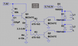
Not too big a deal. Pretty sure this is similar to what J-P has in mind -- just without ordering a Darlington. Hope he approves.
Really the same circuit, but with 2 little changes:
- the capacitor whose charging ramp generates & times the delay is now buffered -- longer delays can still provide more *signal* current, even with smaller capacitors and larger resistors
- the transistors driving the relays are now configured to give voltage AND current gain -- Common Emitter
This requires changing the relay coil wiring. The coil terminal originally connected to the driver Emitter, will now connect to the 5,7V filament supply (um, well -- through the rectifier to add a little drop). The coil terminal originally grounded, will now connect to its driver's Collector. The Emitters are now grounded.
This lessens the effect of differences between relays and driver transistors. They may still not click in the same millisecond, but it won't be a several second gap in between.
Cheers
Attachments
No need for my approval. I think we are way too long occupied by this ultra simple circuit. Anyone doing anything in electronics should learn and know what parallel is. That is why I refused to draw and wanted OP to draw as otherwise not much is learned. I would also use one 6V power rail.
Building a second separate circuit on veroboard and experimenting with this simple circuit would not hurt to gain experience. The whole issue is the "doing something" practice which now dictates changing things in an already built device.
Building a second separate circuit on veroboard and experimenting with this simple circuit would not hurt to gain experience. The whole issue is the "doing something" practice which now dictates changing things in an already built device.
Last edited:
Hey Rick,
Thanks for drawing up the schematic.
I'm looking into getting the parts for it. Why the use of 2 different diodes?
Thanks for drawing up the schematic.
I'm looking into getting the parts for it. Why the use of 2 different diodes?
If you're asking about the Zener (D4), they are *special*. The others could all be 1N400x's, but not 1N4148's. I usually spec the 1N4148, a switching diode, anytime its light-duty ratings are enough -- because many experimenters have some on hand and they are widely available. We already had those installed for the relay coil flyback. (edit: Unless we didn't! 😱 If those are already 1N400x's or similar, it's perfectly fine to leave them.)
But their current rating is not high enough for them to provide the 1-diode-drop for both coil's currents that D3 does.
Zeners have a soft knee in the forward direction, then block current flow in the reverse direction Until their rated breakdown voltage. They're pretty useful -- worth looking it up, if unfamiliar.
Last edited:
I believe i have UN4007 in the circuit now on the relays.
Hopefully that wasn't a problem.
I've ordered a 3.3v zener and some 1N400x. Diodes
Thanks for the explanation. I have used a zener before and have a general understanding of how they work.
Hopefully that wasn't a problem.
I've ordered a 3.3v zener and some 1N400x. Diodes
Thanks for the explanation. I have used a zener before and have a general understanding of how they work.
A UN4007 should be fine for D3, as well. All we care about is the 0,6V drop, so just about any general purpose silicon device will suffice.
Capturing the flyback spike of a small coil is pretty easy duty for just about any diode or rectifier -- there's no way for a UN4007 to be challenged.
Capturing the flyback spike of a small coil is pretty easy duty for just about any diode or rectifier -- there's no way for a UN4007 to be challenged.
Couple little pointers, if I may be so rude ..
Try to resist the urge to place jumpers under any part with a body -- say a relay.😉 Too much of an impediment to changes, whether for redesign, or troubleshooting.
If you place each driver transistor next to the relay it drives, a single trace can serve the node that connects the Zener and 3 resistors, and carry the signal across both relay bodies and out to the timer-buffer area.
Cheers
Last edited:
Rick
I need all the pointers I can get. The reason why i put jumpers under the relays was to save space. I mounted the board vertically and only have limited space.
This circuit will be even more challenging because there's even more components.
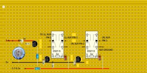
Once I have a veroboard layout i can post the image.
Btw where can i get that jumper material from? I was given some and I'm quickly running out.
Thanks again
I need all the pointers I can get. The reason why i put jumpers under the relays was to save space. I mounted the board vertically and only have limited space.
This circuit will be even more challenging because there's even more components.
Once I have a veroboard layout i can post the image.
Btw where can i get that jumper material from? I was given some and I'm quickly running out.
Thanks again
I have a wide, shallow drawer under the work surface that stays open a few inches (6 - 8 cm) -- every trimmed lead falls right in.
They're several different materials, so, not so good if you need uV accuracy over temperature.
You can get spools of #20, 22, or 24 AWG tinned copper bus wire .. someplace. IIRC it was a local supplier of Belden products last time I bought it.
They're several different materials, so, not so good if you need uV accuracy over temperature.
You can get spools of #20, 22, or 24 AWG tinned copper bus wire .. someplace. IIRC it was a local supplier of Belden products last time I bought it.
- Home
- Amplifiers
- Tubes / Valves
- tube preamp makes rushing noise at speakers