Hi Erik and Soog!
Thanks for the infos.
Could you tell me what could be the operational voltage of Dsavidsk's 5687 preamp?????
Here is the datasheet of the 5687 triode:
http://www.drtube.com/datasheets/5687ge59.pdf
Greets:
Tyimo
Thanks for the infos.
Could you tell me what could be the operational voltage of Dsavidsk's 5687 preamp?????
Here is the datasheet of the 5687 triode:
http://www.drtube.com/datasheets/5687ge59.pdf
Greets:
Tyimo
Hi Lineup!
Thanks!🙂
O.K. Than the value of the Perugini's 6N30 Rload resistor is 100K?
Greets:
Tyimo
Very nice PCB!
Thanks!🙂
But we do not need R9, if we couple the input ( R3 ) to a tube output.
( or any other output WITHOUT cap.
In fact WE MUST remove R9, if using an output that is not at 0V = ground level. )
This makes input impedance of SEWA is = R2 = 100 kOhm.
O.K. Than the value of the Perugini's 6N30 Rload resistor is 100K?
Greets:
Tyimo
Tyimo said:
O.K. Than the value of the Perugini's 6N30 Rload resistor is 100K?
.
Yes, you remove .47u Cap and Rload in that tube amp output.
And you connect 6H30 Tube Pin3 to SEWA R3 resistor.
And of course Ground of tube circuit to GND of SEWA.
Do not make these wires longer than you need.
This is a good rule in all audio regarding wires.
Not longer than we need.
And very correct, the new Rload for the tube output will be R2, 100 kohm, in SEWA.
The input cap in SEWA can still be 1uF. It is not necessary with any higher value.
In fact 470nF (= .47u) would work well, too.
And please, do not forget to REMOVE R9 in SEWA!
This resistor is only for charge the 1uF Cap, if input is unconnected.
The cap will be charged by tube pin 3, when you have them connected.
That is why we can remove R9, 100 kohm.
lineup
I would say that you should be thinking of a B+ of about 200V.
The exact value is not critical because the CCS will self adjust to put the correct voltage onto the plate of the 5687 (its like magic). If you put to little B+ in then the CCS will collapse on large transients and you will get clipping. If you put to much on the in at B+ the constant current source will have difficulty shedding the heat. I can't read the exact value of the cathode resistor which makes it difficult to guess what was intended.
I personally run mine with about 160V B+ (less than I would like - but it works) and use 2 orange LED's for cathode biasing. I recommend this technique for bias as it eliminates the cathode bypass cap (good) and gives a much more fixed bias point. I use LED's for cathode bias on all my projects now. The bass tightens up a lot and detail improves. Build it with the resistor to find out the bias voltage and then substitute LED's when you know.
Hope that helps.
Shoog
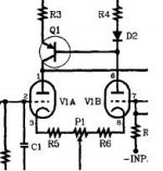
Shoog said:I can't read the exact value of the cathode resistor which makes it difficult to guess what was intended
To me it looks like the left channel 5687 has got cathode resistor 430R and 470 uF across.
Maybe could be 130R ??
See Tyimo 5687 schematic attachment:
http://www.diyaudio.com/forums/attachment.php?s=&postid=1052454&stamp=1163094193
The anode current source looks like targetted at 9-10 mA. ( ~1.0V / 100R )
At 430R I would guess that he's running the thing at fairly low current - though it very difficult to work these things out retrospectively.
If I was building it I would substite a 1K trimmer pot for the 100R resistor in the CCS, this would allow you to adjust the current through the CCS. I would be looking to sink about 15mA through the 5687 in order to get the drive you want. Be careful as you can ask the CCS to deliver to much current and fry the transistors. Once you know the value of the resistor which gives you the desired current, you can substitute a fixed value resistor.
The cathode bias resistor may need to be adjusted to give the right plate voltage. With a B+ of 200V you will want a plate voltage of between 120-150V.
Shoog
Having just looked at the datasheet, my best guess on the operating point is that he is using a 150V on the plate with a bias point of about 6V for a current of about 20mA. That looks very good for what you want. The suggested 200V of B+ should work on this setup.
Two orange LED's should substite very nicely for the 430R cathode resistor.
Shoog
Two orange LED's should substite very nicely for the 430R cathode resistor.
Shoog
Hi Tymo,
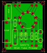
Looks OK except if the view is from the top, the sections are backwards (dead tube on power up) and pin 9 should be grounded.
ECC88:
U1 = 6, 7, 8 - AGK
U2 = 1, 2, 3 - AGK
The Vh-k are different on the sections... 50V for U1 and 150V for U2.
Cheers!
Looks OK except if the view is from the top, the sections are backwards (dead tube on power up) and pin 9 should be grounded.
ECC88:
U1 = 6, 7, 8 - AGK
U2 = 1, 2, 3 - AGK
The Vh-k are different on the sections... 50V for U1 and 150V for U2.
Cheers!
Hi Geek!
Thanks for the infos!
I thought the opposite! U1=1,2,3....
Where can I read about the correct tubesections? Ther is no info in my tube data sheets.
I have to redesign the PCB.
Greets:
Tyimo
Thanks for the infos!
ECC88:
U1 = 6, 7, 8 - AGK
U2 = 1, 2, 3 - AGK
I thought the opposite! U1=1,2,3....
Where can I read about the correct tubesections? Ther is no info in my tube data sheets.
I have to redesign the PCB.
Greets:
Tyimo
Hi Tyimo,
No problem 🙂
I've double checked my books and pdf's, that schematic is in error... in that circuit, it's not critical anyway.
Here's an online pinout where you don't have to download a pdf:
http://www.r-type.org/exhib/aaa0281.htm
IIRC, there is one double triode with section one, being the low numbered pins, but it slips my mind right now as to the number.
Cheers!
Tyimo said:Hi Geek!
Thanks for the infos!
I thought the opposite! U1=1,2,3....
Where can I read about the correct tubesections? Ther is no info in my tube data sheets.
No problem 🙂
I've double checked my books and pdf's, that schematic is in error... in that circuit, it's not critical anyway.
Here's an online pinout where you don't have to download a pdf:
http://www.r-type.org/exhib/aaa0281.htm
IIRC, there is one double triode with section one, being the low numbered pins, but it slips my mind right now as to the number.
Cheers!
Here's an online pinout where you don't have to download a pdf:
Thanks Geek!
I see.
Tyimo
Hello,it´s time for some help again,😎  Been working on this parafeed thing all day
  what I`ve come up with is that the gain is not enough to drive the Sewa to full output,I use 4:1 now.
The sound is a "littla"dark low treble and mid.If I put a condensator at "A" I get the treble amd mid´s again and a little more gain.If I put a condensator at "B" I get a lot of gain,all I need + the treble an mid´s.
But I wonder what effekt on the parafeed does this condensators have?It sounds god with them.Should I use a 1:1 trafos instead?
Been working on this parafeed thing all day what I`ve come up with is that the gain is not enough to drive the Sewa to full output,I use 4:1 now.The sound is a "littla"dark low treble and mid.If I put a condensator at "A" I get the treble amd mid´s again and a little more gain.If I put a condensator at "B" I get a lot of gain,all I need + the treble an mid´s.
But I wonder what effekt on the parafeed does this condensators have?It sounds god with them.Should I use a 1:1 trafos instead?
An externally hosted image should be here but it was not working when we last tested it.
Hi Tyimo,
Looks better 🙂
Nah, you only need one. I like big caps, but if you already have the 1uF or can't budget for the bigger one, no problem. As long as it can handle the peak DC voltage + AC.
P.S. Can I get a couple boards from you? 😀
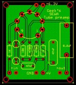
Tyimo said:Here is the corrected PCB plan. I hope now everything are O.K.🙂
Looks better 🙂
One more question: if I have in the SEWA an 1uF inputcap, than need I use the 8.2uF output cap in your preamp too?
Nah, you only need one. I like big caps, but if you already have the 1uF or can't budget for the bigger one, no problem. As long as it can handle the peak DC voltage + AC.
P.S. Can I get a couple boards from you? 😀
Hi Geek!
Thanks for the helps!
Yes!🙂 Send me your address and when I will be ready (in couple of weeks)I will send you.
Greets:
Tyimo
Thanks for the helps!
P.S. Can I get a couple boards from you?
Yes!🙂 Send me your address and when I will be ready (in couple of weeks)I will send you.
Greets:
Tyimo
- Status
- Not open for further replies.
- Home
- Source & Line
- Analog Line Level
- Tube Pre Amplifier for SEWA 7 Watt ClassA MOSFET