i have two tube amps with a 10 henrys choke in the power supply of the output transformer.
I have read that using a capacitor connected in parallele on the choke is going to kill more the 100 hz ondulation of the power supply.
i have calculated the value of this capacitor .
It is 0.25 µf (using for calculation LCsquare w=1)
But are they any drawbacks or disavantages in doing that ?
thanks
Where did you find this suggestion?
It seems to me, this would only serve to reduce the effectiveness of the choke. But perhaps there is something I'm missing.
It seems to me, this would only serve to reduce the effectiveness of the choke. But perhaps there is something I'm missing.
it is usual in electronics to use what we call in french "un circuit bouchon" to kill one particular frequency. this circuit combine a choke and a capacitor connected to the two poles of the choke. The value of the choke,of the capacitor and the frequency to damp are connected by the formula i mentioned.
A tuned choke (i.e. capacitor in parallel) can reduce 100Hz ripple, but increase higher frequencies (200Hz, 300Hz etc.). This techniques is rarely used nowadays.
I have the same knowledge as DF96. It will kill very well the frequency at which the inductor is tuned, but much less attenuation for the rest.
Or… in the famous words of (who knows…), “there's no free lunch”.
The capacitor-in-parallel-with-inductor as a notch filter does indeed increase the attenuation of the 'notch' frequency defined as
Outside that notch though, the filter rapidly stops filtering. Almost all of the harmonics above 100 Hz will be passed. Which is precisely what you don't want, since they buzz and make an awful din.
So…
C → L → C → L → C
An outstanding filtering topology that needn't cost a fortune. Or, if you prefer, just CLC.
Just Saying,
GoatGuy ✓
The capacitor-in-parallel-with-inductor as a notch filter does indeed increase the attenuation of the 'notch' frequency defined as
F = 1/(2π√(LC))
F = 1/(2 √(10 Hy × 0.00000025 F))
F = 100.66 Hz
which in this case is right where you in a 50 Hz line frequency country might want the notch. (Even here, then there's the idea of 'Q', which is markedly lowered by the series resistance of the inductor (significant) and the ESR of the capacitor (not very large). The equation gets much more squirrelly, but basically the depth of the notch is related directly to the 'Q' of the resonant circuit.)F = 1/(2 √(10 Hy × 0.00000025 F))
F = 100.66 Hz
Outside that notch though, the filter rapidly stops filtering. Almost all of the harmonics above 100 Hz will be passed. Which is precisely what you don't want, since they buzz and make an awful din.
So…
C → L → C → L → C
An outstanding filtering topology that needn't cost a fortune. Or, if you prefer, just CLC.
Just Saying,
GoatGuy ✓
But if the filter is an inductor with a parallel capacitor and a capacitor at each end to reurn wire, the ratio of the caps defines the ratio of impedances, and hum attenuation, but also participates in the tuning formulae. If I don't remember bad, it is called m-derived topology.
Yep. Just as you say.
Outside that notch though, the filter rapidly stops filtering. Almost all of the harmonics above 100 Hz will be passed.
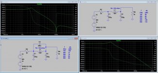
This may be a bit of an exaggeration. Below two CLC-filters, one typical, the other with the 100 Hz notch. The attenuations are written on the schematics.
The minimum attenuation of the filter with notch is improved some 6...7 dB
if 220 uF capacitors are replaced with 330 uF.
Attachments
This technique may be useful if you need unusually low hum, you can use a CLCLC filter (with one choke tuned), and you are exceptionally good at getting grounding right (poor grounding would inject far more hum than the choke will remove). Unlikely for audio. These days we just use bigger caps instead.
Great! Try not to forget that the Q of the tank circuit also is a measure of the increased voltage blocking requirement of the non-polar (remember?) capacitor sitting across the inductor.
The formula for Q is
Just Saying,
GoatGuy ✓
The voltage magnification that takes place at resonance is given the symbol Q and the "Q Factor" (the voltage magnification) of LC Band Pass and Band Stop filter circuits for example, controls the "rejection", the ratio of the wanted to the unwanted frequencies that can be achieved by the circuit.
The effects of voltage magnification are particularly useful as they can provide magnification of AC signal voltages using only passive components, i.e. without the need for any external power supply.
In some cases voltage magnification can also be a dangerous property. in high voltage mains (line) operated equipment containing inductance and capacitance, care must be taken during design to ensure that the circuit does not resonate at frequencies too close to that of the mains (line) supply. If that should happen, extremely high reactive voltages could be generated within the equipment, with disastrous consequences for the circuit and/or the user.
The Q factor can be calculated using a simple formula. The ratio of the supply voltage VS to either of the (equal) reactive voltages VC or VL will be in the same ratio as the total circuit resistance (R) is to either of the reactances (XC or XL) at resonance. The ratio of the reactive voltage VL to the supply voltage VS is the magnification factor Q.
The formula for Q is
Q = I²X / I²R … which isn't terribly helpful, but also
Q = √(L/C) / R which also simplifies to
Q = √(L/R²C); which for your component mix becomes
Q = √(10 /( 50² × 0.25×10⁻⁶ ) );
Q = 125
Which is one heck of a voltage multiplier. Putting that into perspective, the smallish A/C injection shown on your SPICE simulation diagram (20 volts, 100 Hz) is first going to be filtered by the 20 Ω front series resistor and the 220 µF capacitor to Q = √(L/C) / R which also simplifies to
Q = √(L/R²C); which for your component mix becomes
Q = √(10 /( 50² × 0.25×10⁻⁶ ) );
Q = 125
Z = 1/(2πfC)
Z = 1/(2 × 3.1415 × 100 Hz × 220×10⁻⁶ F)
Z = 7.24 Ω
and in a voltage divider (not quite correct, but close)Z = 1/(2 × 3.1415 × 100 Hz × 220×10⁻⁶ F)
Z = 7.24 Ω
VAC-at-L = VAC × 7.24 / (20 + 7.24);
… = 20 × 7.24 ÷ 27.24
… = 5.3 V, and now multiplied by Q
VPEAK = 5.3 × 126
VPEAK = 667 V
See what I mean? At resonance, the internal voltage can be REALLY large. This is the same principle used in building radio antennae. Basically, putting a capacitor in parallel of the 'helpful' value, causes the antenna to sympathetically oscillate. The resulting voltage measured across the resonant antenna can be many dozes of times higher than the actual RF voltage. … = 20 × 7.24 ÷ 27.24
… = 5.3 V, and now multiplied by Q
VPEAK = 5.3 × 126
VPEAK = 667 V
Just Saying,
GoatGuy ✓
This circuit (CLC with notch) maybe differs a lot from pure band stop filter, since the notch is located at the frequency where attenuation is already quite high due to 2 x 220 uF capacitors.
The simulation shows only some 12 Vpp across the inductor/250 nF capacitor.
The simulation shows only some 12 Vpp across the inductor/250 nF capacitor.
...The attenuations are written on the schematics.....
Good; because the two graphs came out different scales and it is hard to compare them.
(Your sim can't plot two lines on the same graph? Draw the circuit both ways and drop two probes?)
Also we don't expect milli-Hz coming in. Yes the bump at the corner may have significance but is the same with/without tuning. I have denoted the expected harmonics because that's what we need to reduce. (Assumed 100Hz power.)
My re-plot shows much less 100Hz but easily 20dB-30dB more at 300Hz up. Depending on room, speakers, listener, this lower midrange hash can be more annoying than the 100Hz partial.
An aside: this plan does have merit *for TV* where the 100Hz wants to beat with the vertical scan and make the image "hop".
Attachments
'Cathode Ray' (aka Scroggie) did a write up in WW Nov 1949, along with a measured result.
https://americanradiohistory.com/Archive-Wireless-World/40s/Wireless-World-1949-11.pdf
https://americanradiohistory.com/Archive-Wireless-World/40s/Wireless-World-1949-11.pdf
Thanks. We can trust Scroggie. I don't see that his curve is measured (it smells calculated). And *note* that he uses 8uFd not 220uFd, and he uses more *sections* than the sims run in post #8 here. So his curves start with less initial (50cps) attenuation, but have steeper slopes. (And are drawn upside-down from the way the sim plots it.)
It is interesting that the modern big-cap few-stage plan, and the 1949 plan, arrive at similar filtering at 800Hz (where it hurts). Do note that both are tutorial examples and not necessarily fit for any specific purpose.
It is interesting that the modern big-cap few-stage plan, and the 1949 plan, arrive at similar filtering at 800Hz (where it hurts). Do note that both are tutorial examples and not necessarily fit for any specific purpose.
Attachments
Just my opinion, but if you need a power supply so quiet that a CLC filter with suitably large capacitors is not quiet enough, regulate it. Regulating power supplies like this is fairly easy and inexpensive with modern semiconductors. If you just need low noise, the "capacitance multiplier" using a suitable MOSFET can work quite well.
One of the best things about a choke in tube power supplies is that it really helps to filter out all the high frequency crap that's on power lines (Mostly due to cheap and poorly designed SMPS). Putting a cap in parallel with the choke will reduce its effectiveness in this area. That's not to say this isn't a useful technique in some circumstances, but certainly not all.
One of the best things about a choke in tube power supplies is that it really helps to filter out all the high frequency crap that's on power lines (Mostly due to cheap and poorly designed SMPS). Putting a cap in parallel with the choke will reduce its effectiveness in this area. That's not to say this isn't a useful technique in some circumstances, but certainly not all.
I liked Scroggie commenting on a few items such as balancing the rectifier to suppress some discernible 50Hz. I'd suggest that few appreciate the variation in secondary half-winding DCR values unless they measure them to get say a PSUD2 parameter value, or the variation that can occur with tube rolling dual diodes - and even fewer would have a spectrum analyser at the ready to confirm minimum 50Hz - it almost seems like a humdinger is worthwhile.
However I would suggest that tuning is done to suppress 100Hz at idle operating current, as that would be perhaps the most discernible time to hear that hum, rather than tuning for max loading through the choke.
With respect to the effective Q, we don't really know from the OP what the DCR is, or what current the choke is rated for, so 50 ohm is just a guess. Plus there is some advantage to adding series resistance to the C, so as to lower the Q and to improve high frequency attenuation a titch.
What the article didn't add any comment on was how to actually tune the filter, given the inductance may vary noticeably over the load range. Scroggie just comments about the flatness of the tuning, due the sq-rt of L. It may not be that safe to accurately tune (if that is what one is after) as it could require some switched capacitor configuration and iteration, plus a spectrum analyser to confirm what is happening to the 100Hz level.
Last edited:
I use regulated power supplies using the old gas discharge valves.Just my opinion, but if you need a power supply so quiet that a CLC filter with suitably large capacitors is not quiet enough, regulate it. Regulating power supplies like this is fairly easy and inexpensive with modern semiconductors.
One of the best things about a choke in tube power supplies is that it really helps to filter out all the high frequency crap that's on power lines (Mostly due to cheap and poorly designed SMPS).
If the G2 supply is not demanding it works perfectly DIRECT.
Otherwise I wired one of those GEC stabiliser triodes in, with the gas stab feeding the triode grid and it does a superb job.
The other thing which is out of fashion but it stunningly effective is choke input filters.
You get hum free supplies with as little as 4-8uF smoothing.
Those technqiues beats C-L-C any day of the week, and cost peanuts.
No, not in this case. If you apply a voltage across a parallel LC circuit then the maximum voltage you will see is the applied voltage. In the case of a tuned choke in a typical cap input PSU we are talking about tens of volts at most.GoatGuy said:See what I mean? At resonance, the internal voltage can be REALLY large.
To get high voltages you need to inject a current i.e. from a high impedance source.
Exact tuning is not needed. All you need is a significant rise in impedance at the operating frequency. You could tune the choke to 200Hz and still get a small rise in impedance at 100Hz; all frequencies below resonance see a rise in impedance.
That may or may not depend on the available mix of harmonics, the actual filtering component impedances and their variation with frequency, the noise floor, and the final aim of the exercise. Back in Scroggie's day one would have had an averaging AC voltmeter and ears. Nowadays a spectrum analyser can be connected if one was keen.Exact tuning is not needed.
- Home
- Amplifiers
- Tubes / Valves
- tube power supply and chokes