hi eric,
pls free to call my mobile tomorrow for setting!
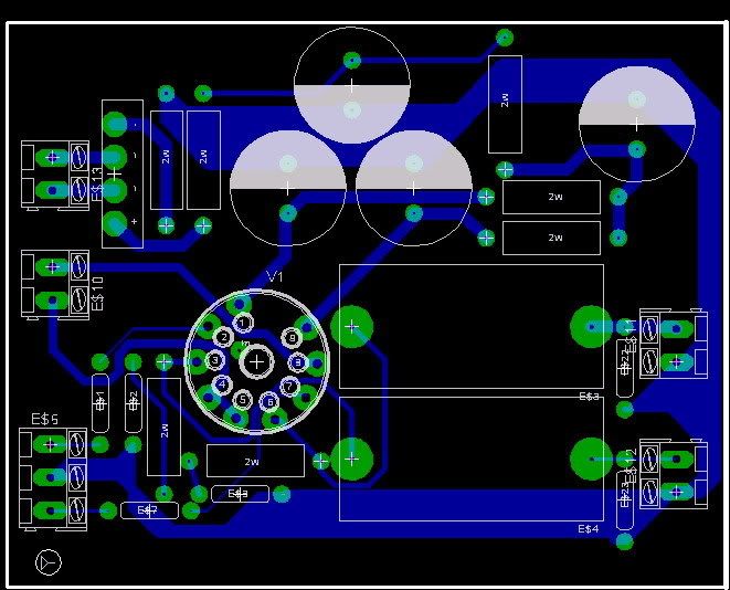
BTW, tube buffer was printing.
Take a look of the NEW tube buffer PCB.
Increase ground area, parts size( easy to upgrade large size parts & re-lay out!
thx
thomas
pls free to call my mobile tomorrow for setting!
BTW, tube buffer was printing.
Take a look of the NEW tube buffer PCB.
Increase ground area, parts size( easy to upgrade large size parts & re-lay out!
thx
thomas
tube-lover said:
BTW, tube buffer was printing.
Take a look of the NEW tube buffer PCB.
Increase ground area, parts size( easy to upgrade large size parts & re-lay out!
Great, Thomas. When will the PCBs be ready for shipping, on your opinion? And, ant news about the tube mono power amps?
Bye Thomas!
hi kooda,
since I was very small order. PCB Factory that I choose was a large firm. They are not too care for my order. But i call to them to push them already.
For the small Mono Block.
Take a look of the power transformers & OPT, same size but different quality of core.
OPT will use Z11
( Hi-grade) Nippon steel Lamination for low core loss.
( Use Ultra Thin 0.1mm bamboo layered paper with natural bee wax to lower the capacitance & increase MF Vocal density)
Bifilar wound Interstage C-core interstage 1+1:1+1 Z11
( Hi-grade) Nippon still Laminations for low core loss.
( Use Use Ultra Thin 0.1mm Natural Bamboo layered paper with natural bee wax to lower the capacitance & increase MF Vocal density)
Power transformers use copper foil double shielding low noise c-core power transfomers.
Choke ( 5H 120ma) Standard Z11 lamination
take a look for the size of the OPt & power trans.
thx
thomas
An externally hosted image should be here but it was not working when we last tested it.
hi kooka,
don't worry the outlook,
I will not use black ugly look.
all Trans will enclose ( full potted) with hammer Tone chassis.
take a look for the protype.
choke will inside the chassis.
It means every mono block will contain 4 pcs of transformers.
thx
thomas
don't worry the outlook,
I will not use black ugly look.
all Trans will enclose ( full potted) with hammer Tone chassis.
take a look for the protype.
choke will inside the chassis.
It means every mono block will contain 4 pcs of transformers.
thx
thomas
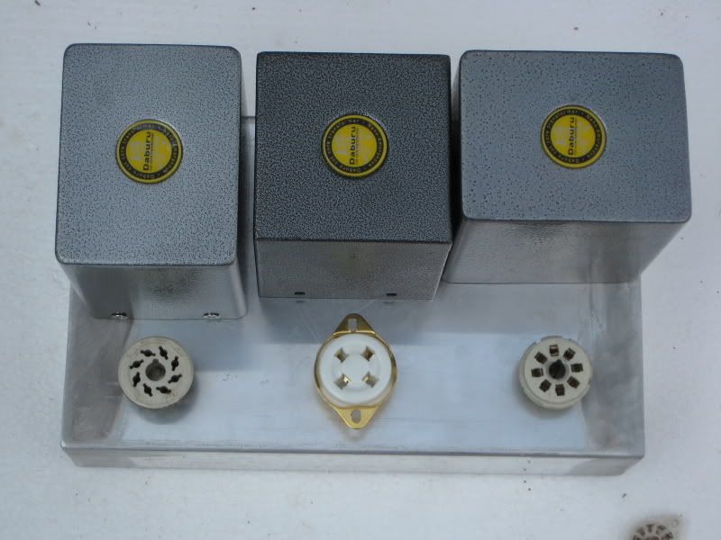
this chassis will paint later,
this is protype. I was arranged the loaction of every parts inthe surface of the chassis.
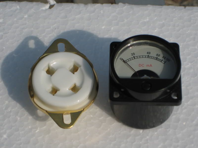
This is tailor made small ma meter.
small & same size of the tube socket.
I like slim size & mono block, because can put close to speaker.
thx
thomas
this is protype. I was arranged the loaction of every parts inthe surface of the chassis.
This is tailor made small ma meter.
small & same size of the tube socket.
I like slim size & mono block, because can put close to speaker.
thx
thomas
this is one of my reference data,
but I will not choose it circuit, I like use Interstage but not like to use 6L6 triode connection.
thx
thomas
but I will not choose it circuit, I like use Interstage but not like to use 6L6 triode connection.
thx
thomas
An externally hosted image should be here but it was not working when we last tested it.
another circuit for my reference.
But I not like to use feedback & 6BM8 to drive for 811. I was worry the swing is not too enough!
thx
thomas
But I not like to use feedback & 6BM8 to drive for 811. I was worry the swing is not too enough!
thx
thomas
An externally hosted image should be here but it was not working when we last tested it.
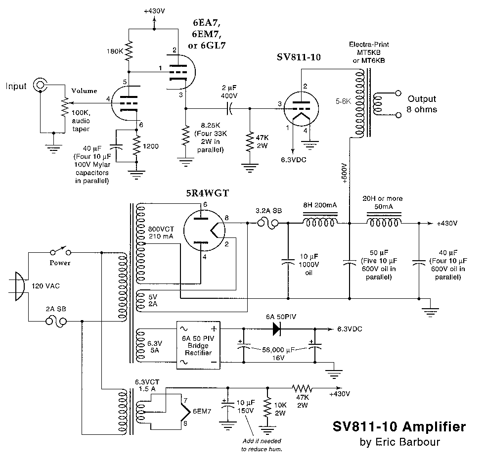
finally I was testing for this.
Use 1:1 Bifilar Interstage to relief the 2uf coulping capacitors.
power transfomer filament winding use 0~7.5v ( can supply 5V to 300B & 6.3V to sv-811).
OPT use 3.5K~5K primary loading.
Then this crcuit can use either 300b or SV-811-10/SV-811-3.
User will had two choice!
thx
thomas
Use 1:1 Bifilar Interstage to relief the 2uf coulping capacitors.
power transfomer filament winding use 0~7.5v ( can supply 5V to 300B & 6.3V to sv-811).
OPT use 3.5K~5K primary loading.
Then this crcuit can use either 300b or SV-811-10/SV-811-3.
User will had two choice!
thx
thomas
Thomas, seems you are doing a great job here. Keep on the good work... and rememeber I will be in HK by march... be ready😉
Hi Thomas,
Thank you. I will call you.
For the tube buffer, you may design a full balance tube buffer, so 4pcs of PCB will be used for one full balance dac. It may help you to boost the sales in order to fulfill the production volume.
Regards
Eric
Thank you. I will call you.
For the tube buffer, you may design a full balance tube buffer, so 4pcs of PCB will be used for one full balance dac. It may help you to boost the sales in order to fulfill the production volume.
Regards
Eric
Hi Thomas or anyone who know,
Just to check the DAC balance output's polarity. Is one of the output with inverted polarity?
I would like to have 2 set of RCA out for active crossover and sub. Wonder if I can use the balance board for that. No good if polarity been inverted.
Thanks 😀
Just to check the DAC balance output's polarity. Is one of the output with inverted polarity?
I would like to have 2 set of RCA out for active crossover and sub. Wonder if I can use the balance board for that. No good if polarity been inverted.
Thanks 😀
Hi kokheng,
Have a look at my wiring on post #60, your wiring should be the same.
http://www.diyaudio.com/forums/showthread.php?postid=1353606#post1353606
If your wiring is correct, try to measure it again and this time with the 'black' prob on the main earth, not neutral.
Do tell us more about your problem.
btw... which part of M'sia you in? Good to see diy from M'sia. I'm from M'sia too, been here in NZ for 19 yrs......
Hi SamL,
Nice to know that you are fr Msia too....... I'm from Klang, Selangor
The 9V transformer is fine, giving 11.4V output. I only get 9.6V output from the 15V transformer, if i'm not mistaken, I got the same problem with gomi2......
Both the trans are with my friend now for checking, I told him your idea aand will let you know the outcome.
Thanks
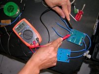
hi i'm friend of kok heng.
When i connected exactly as you show in photo, i still get 9.6v from the 15v secondary.
1) When the 15v 2ndary still not connected in series, the 0-15 and 1-5 only give 9.6v.
2) when i connect both 9v transformer and the 15v transformer in the same way, the 9v transformer give 11.4v, and the 15v transformer give on 9.6.
3) when black probe on main earth at 3 pin socket, it give ~33v, red on 16v (pcb socket)
4) when black probe on earth point at pcb, red at 16v pcb socket, it read 9.6V
so do u think i shall connected the main earth to the 0 at the 16-0-16 socket?
dear all,
can it be the 15v transformer we recieved is actually a 9V transformer where it was wrongly printed as 15v? both transformer is same in size.
dear tube lover,
do u cehck the output of both transformer before you send it out?
can i run the DAC 16-016 at 11.6-0-11.6 meaning shifting the transformer?
Hi KokHeng,
I am not sure if those trans are from this company "YHDC'...if yes, you may like to see this page http://www.yhdc.com/gscp/16-17_e.htm for the pins configuration.
Best Regards
S K
I am not sure if those trans are from this company "YHDC'...if yes, you may like to see this page http://www.yhdc.com/gscp/16-17_e.htm for the pins configuration.
Best Regards
S K
Hi all,
when the coaxial cable was connected to player, meaning the ground is establish teh reading as below:
1) for 15V transf: is 9.6v-0-9.6v regardless the balck probe is on main earth or at the 0v point. When use as AC without center tap it is 9.6vAC. 1probe tomain earth, 1 probe to one of the pin=~4.8vac
2) for 9V transformer it is 11.4 V.
Then i measure the resistant at each secondary coil for both 15v transf & 9v transf
a) 15v transf: ~0.3 Ohm
b) 9V transfr: ~0.7 Ohm
By right the 15V transformer shall has higher resistant as it use more coil. That what i suspect the 15v transformer we received is a 9.4 v transformer and the 9v transformer we received is actually a 11.3v transf
if we refer to factory website the supply 9.4v X 2, 11.3v X 2 and 15V X 2 in the same casing size. So there's chance they may printed wrongly.
I had try running the 16-016 using the 9V transf which provide 11.40-11.4v, and runing the 9Vac with 15V transf which give output of 9.6V. The DAC is working but i'm not sure and negative effect running this way...
kindly advise.
TQ
windwss said:
3) when black probe on main earth at 3 pin socket, it give ~33v, red on 16v (pcb socket)
4) when black probe on earth point at pcb, red at 16v pcb socket, it read 9.6V
so do u think i shall connected the main earth to the 0 at the 16-0-16 socket?
I am sure this is the same as my transformer on post#60. The reading there was taking with black probe on main earth.
I connect the 16-0-16 transformer to power pcb as per my post. So far I have no major problem. One of the LM317 do run quite hot but it is unlikely to do with less power. I am on running dual opamp IV on SE version.
The transformer is not as high quality as I though as it hamming louder than my 100w power amp. Well, since there no noise coming out at the volume... I'm keeping it for now.
- Status
- Not open for further replies.
- Home
- Source & Line
- Digital Source
- Tube-lover SE and Full Balance TDA1541a DAC