Funny that Lukasz Fikus is trusted by so many of us to have discovered a miracle output stage when he has made so many mistakes.
I am reassured by your listening impressions, Oliver, and quite excited to hear it. To build this, I sold my DAC, so am now listening to my excellent system through a horrid Sony minidisc player, used as a dac, with a distinctly op-amp sound. Yeurch! My hi-fi has never sounded so horrible, if I'm honest. All good motivation 😀
I am reassured by your listening impressions, Oliver, and quite excited to hear it. To build this, I sold my DAC, so am now listening to my excellent system through a horrid Sony minidisc player, used as a dac, with a distinctly op-amp sound. Yeurch! My hi-fi has never sounded so horrible, if I'm honest. All good motivation 😀
Funny that Lukasz Fikus is trusted by so many of us to have discovered a miracle output stage when he has made so many mistakes.
Hey, i don´t said that he made any mistake with his I/V resistor value!
If you read his Lampizator doc.
 you see, that his R I/V values are with tolerances between +10/-50%.
 So we are pretty good in that window. 😉
HV-Shunt Module Pre-Order for 2nd Batch:
-----------------------------------------
Jean-Charles - 2x
kamaths - 3x
bequerel - 2x
morpheous - 2x
ksnider1 - 1x
ipolyakov - 2x
savvas - 2x
hawall841 - 1x
NeoInc - 1x
-----------------------------------------
Jean-Charles - 2x
kamaths - 3x
bequerel - 2x
morpheous - 2x
ksnider1 - 1x
ipolyakov - 2x
savvas - 2x
hawall841 - 1x
NeoInc - 1x
Sure, I really don't mean to criticise him, as I find his site perhaps the most honest, readable and interesting personal hi-fi site I have found on the web, and I am sure this circuit is very good indeed, but surely he will be inviting distortion with such a high i/v value and output voltage, no?
HV-Shunt Module Pre-Order for 2nd Batch:
-----------------------------------------
Jean-Charles - 2x
kamaths - 3x
bequerel - 2x
morpheous - 2x
ksnider1 - 1x
ipolyakov - 2x
savvas - 2x
hawall841 - 1x
NeoInc - 1x
Ryssen - 2x
-----------------------------------------
Jean-Charles - 2x
kamaths - 3x
bequerel - 2x
morpheous - 2x
ksnider1 - 1x
ipolyakov - 2x
savvas - 2x
hawall841 - 1x
NeoInc - 1x
Ryssen - 2x
HV-Shunt Module Pre-Order for 2nd Batch:
-----------------------------------------
Jean-Charles - 2x
kamaths - 3x
bequerel - 2x
morpheous - 2x
ksnider1 - 1x
ipolyakov - 2x
savvas - 2x
hawall841 - 1x
NeoInc - 1x
Ryssen - 2x
WhiteBull - 2x
-----------------------------------------
Jean-Charles - 2x
kamaths - 3x
bequerel - 2x
morpheous - 2x
ksnider1 - 1x
ipolyakov - 2x
savvas - 2x
hawall841 - 1x
NeoInc - 1x
Ryssen - 2x
WhiteBull - 2x
sorry i was out for the we.Is he using same circuits combination set up and reg values as you do?
yes i'm using exact values as oliver, same bom etc..
since i have another board already populated i'll try this one and see what happens...
Don't use heater lifter dividers right at the reg's output. Tap off DC from its input for that.
On my HV shunt, my 840 is warm but my 9610 has no heat in it whatsoever. Is this normal?
Outputting fine. Stable at 150VDC out with 180VDC input.
Outputting fine. Stable at 150VDC out with 180VDC input.
Hi Salas. Thanks for responding.
Is R1 the current adjust resistor? Resistor numbers are not noted on the PCB, nor do we have a schematic in this thread. I have just looked at your HV shunt thread to check, and it seems that the schematic shows R1 to be a current adjust, but that it should be a 1W resistor, and also that the mosfet is an IRFP9240, whereas this one is using a 9610, like I already said, so I can only refer you to Oliver's PCB photos on page 20 of this thread.
Current adjust is an audio type 1/4 watt PRP, rated at 56R with 1.855v across it.
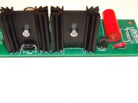
Correction - had it on for about an hour now - fairly warm, so no worries, but nowhere near as toasty as the other transistor (840), which I am feeling may need a bigger sink for longevity. Photos coming...
I post the schematic this evening.
At the moment i'm waiting to my flight from
Sardinia back home.

At the moment i'm waiting to my flight from
Sardinia back home.
Hi Salas. Thanks for responding.
Is R1 the current adjust resistor? Resistor numbers are not noted on the PCB, nor do we have a schematic in this thread. I have just looked at your HV shunt thread to check, and it seems that the schematic shows R1 to be a current adjust, but that it should be a 1W resistor, and also that the mosfet is an IRFP9240, whereas this one is using a 9610, like I already said, so I can only refer you to Oliver's PCB photos on page 20 of this thread.
Current adjust is an audio type 1/4 watt PRP, rated at 56R with 1.855v across it.
Correction - had it on for about an hour now - fairly warm, so no worries, but nowhere near as toasty as the other transistor (840), which I am feeling may need a bigger sink for longevity. Photos coming...
That is R1, and the 9610 is indeed in the newer schematic. If it is running low current like 40mA even 1/4W will do. 1W is there because R1 maybe chosen for whatever current. You should always allow 25mA for staying in the reg above your top consumption in the served audio circuit. ICCS=VR1/R1. Now you got 33mA. The 9610 has 30V across as you report when the 840 has 150V. Guess which one owes to be hotter. The 840 will be significantly less hot when the reg will be loaded and the shunt current will be routed to the load for its most part. Know your full consumption+25mA and choose R1 for each application in brief.
Thanks again Salas.
So, if I am pulling 33mA with this 56R:
Allowing 25mA for the shunts gives me 8mA for the both tubes, which is good I think - this is current to voltage buffer tube, and if I remember correctly it only pulls about 3mA per channel.
I will re-sink that 840 though.
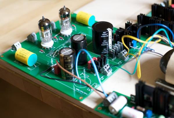
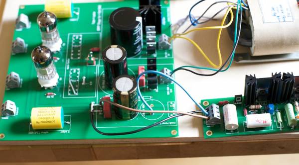
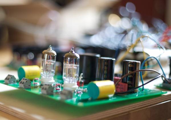
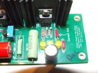
Here's some nice pics of losing my tubes virginity:
 [/IMG]
So, if I am pulling 33mA with this 56R:
Allowing 25mA for the shunts gives me 8mA for the both tubes, which is good I think - this is current to voltage buffer tube, and if I remember correctly it only pulls about 3mA per channel.
I will re-sink that 840 though.
Here's some nice pics of losing my tubes virginity:
Last edited:
Nice pictures! 150*0.028=4.2W dissipation. Don't expect such a sink to feel cool. Then again the 840 is a dog at such Celcious. What is it on the sink? 60C?
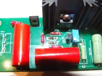
a little update: just swapped the boards, same exact results, adjusting the trimmer result in the same behaviour (Vin=Vout-2v approx.)
any ideas??? i followed exactly the print on the pcb for components positioning.. i'll post a close up, perhaps i'm missing something...
edit: added pics
any ideas??? i followed exactly the print on the pcb for components positioning.. i'll post a close up, perhaps i'm missing something...
edit: added pics
Attachments
Last edited:
Do you have enough current? Measure across R1. 2 guys showing working same stuff, you must be having/doing something different.
- Home
- Group Buys
- Tube-I-zator Professional PCB