Hello Oliver,
i have a strange behaviour of the shunt: it is supposed that i have a Vin and a Vout, let's say that i have 240v Vin, if i adjust the trimmer to have Vout=220 the Vin drops down and Vout is always approx Vin-2v
any ideas?
Did you solder the MJE350 in the right way? Look at my photos. Perhaps you could post a photo of your pcb.
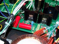
What is that teflon FT1 like cap in the output doing? How is it wired?
Uhh...😱 What is that?
It should look like this:
An externally hosted image should be here but it was not working when we last tested it.
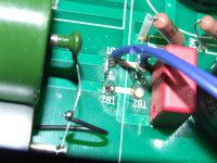
it is shunted to the k75-10 in the output stage, after the tubes as is supposed to be...What is that teflon FT1 like cap in the output doing? How is it wired?
output of the shunt goes to tb1, jumpered to tb2, like your pics
Attachments
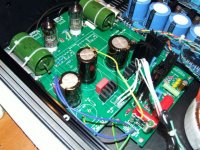
There is something resistor and capacitor next to the red output cap on the reg. What is that doing?
is the voltage reference for the heaters since cathode to heater Vmax was over datasheet specs.
anyway the reg was behaving this way before i added it
anyway the reg was behaving this way before i added it
Did you turn the trimmer both ways? Maybe you give it more current to its ref the side you turn it and it tries to go over its input potential?
sure..after turning it on i turn the trimmer to have the highest Vout, then i turn the trimmer until desired tension...
There are Zeners. One bigger across the 9610, and some small near both Mosfets. Check orientations. Take them out if they are put right and it still does not work properly.
Any news?
Perhaps you could insert a 1K8/5W resistor in series to the input.
So the voltage should drop from 240V to ~170V.
Then you get rid of the voltage reference for the heaters and try it again.
Perhaps you could insert a 1K8/5W resistor in series to the input.
So the voltage should drop from 240V to ~170V.
Then you get rid of the voltage reference for the heaters and try it again.
On the photos it seems so. As far as i saw it, he use also the 6N2P tubes and the reg is soldered with the same values for the R´s.
Oliver,
Regarding i/v resistors. I am thinking about the values. Did you try different values yet? I know that Lukasz Fikus's excitement about this circuit (which is why we're all making it, let's be honest) was with using 100R i/v resistor for a single dac, which is about twice the 56R value recommended here. What i the reasoning behind the given values please? I am due to fire up very soon (just waiting on the teralink X2 now 🙂 🙂 🙂 ) and I have 27Rs installed in the Tub-I-Zator, but I'm not sure why not Fikus's 50R...
Excitedly, Lucas 😀
HV-Shunt Module Pre-Order for 2nd Batch:
-----------------------------------------
Jean-Charles - 2x
kamaths - 3x
bequerel - 2x
morpheous - 2x
ksnider1 - 1x
ipolyakov - 2x
savvas - 2x
hawall841 - 1x
-----------------------------------------
Jean-Charles - 2x
kamaths - 3x
bequerel - 2x
morpheous - 2x
ksnider1 - 1x
ipolyakov - 2x
savvas - 2x
hawall841 - 1x
Oliver,
Regarding i/v resistors. I am thinking about the values. Did you try different values yet? I know that Lukasz Fikus's excitement about this circuit (which is why we're all making it, let's be honest) was with using 100R i/v resistor for a single dac, which is about twice the 56R value recommended here. What i the reasoning behind the given values please? I am due to fire up very soon (just waiting on the teralink X2 now 🙂 🙂 🙂 ) and I have 27Rs installed in the Tub-I-Zator, but I'm not sure why not Fikus's 50R...
Excitedly, Lucas 😀
The TDA1541A has a typical full scale current of 4mA. with the 56R you get a max. output voltage 224mV amplified by x100 (6N2P).
That´s more than enough output voltage 😀
- Home
- Group Buys
- Tube-I-zator Professional PCB