That RPF is a good choice.It needs (like the IRL), worst case, 5V Vgs.So, with lowest voltage on the source 6,5V, you can't loose much voltage in the driving circuit.I think the RFP12N10L might be a good fit for that circuit.
I still have a load of KC811 dual NPN tranistors and im thinking of modifying that circuit with a transistor Long tailed pair.
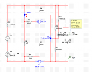
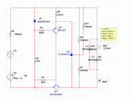
At start-up the PNP is saturated, gives max Vgs. When the 431 sense the voltage is high enough it starts pulling the PNP emitter down until the Vgs is droped to get the right current to keep the output at 6,3V.
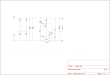
Mona
Ideally you would use a PNP long tailed pair, with a LM385-1.2 as reference, as i think a PNP Long tailed pair could drive the transistor directly.
Discrete transistor versions have some benefit over the TL431 which becomes high impedance after 100Khz, at the expense of DC voltage accuracy, but luckily tube heaters wont mind a +-1% difference at all.
While im at it, i could spread the gospel of the 2SC6144 that is a BJT without the nasty capacitances of a fet, its miller is about 1/4th of that of even the RFP part.
The RFP>=IRL520n in therms of SOA and transfer characteristic linearity. whilst the IRL520n has way better reverse transfer capacitance, and hence is easier to drive. Both are however beaten by 2SC6144 at >=1A and in therms of linearity and reverse transfer capacitance, at the expense of requiring <=5mA base current per Ampere of output current.
anyone wants to try power bricks? 100-240vac pirmary to 5v 4A output, good for 300b.....
i saw a SE amp design posted a while back using this heater supply....https://shopee.ph/product/119376402/6508212791
i saw a SE amp design posted a while back using this heater supply....https://shopee.ph/product/119376402/6508212791
Attachments
[/I][/B]
I think you are selling us all short!! I do listen, but have never found the time to listen to different filament power configurations. My instinct is that providing you have no leakage issues between cathodes and heaters, the differences will be pretty small, and probably far smaller than many other more immediate considerations such as getting hum minimized, operating points optimized, power output adequate for the load etc.
me too, knowing that you did due diligence designing/engineering, making sure nothing fell into the cracks, and being secure in the knowledge that you did your best....
so then who cares? it may sound funny to you, but i liked it and that is all that mattered to me...
That's no good, is positive feedback.
You get emitter-base (driving PNP)-zener-saturated pass-transistor over the input.
Mona
You're right, i glossed over that in my excitement. I should re-check before i post.
Micrel makes a handy regulator chip meant for driving low on resistance mosfets. The MIC5156 http://ww1.microchip.com/downloads/en/DeviceDoc/mic5156.pdf
I have started a design around the MIC5156. Without current limiting as a fuse will work just as well, and if i use my favorite mosfet the IXTH80N075L2 PDF here: https://www.tme.eu/Document/99f7946ab6dae0c37a60411001520f71/IXTA(H,P)80N075L2.pdf
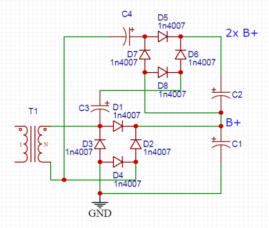
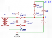
However the 5156 might be the cheapest adj prefix part available, it lacks the charge pump of the others in the series. My workaround is to use a TO247 logic level fet. EDIT, This wont be needed if i can run a voltage doubler and a bridge from the same winding. I only need several mA for the gate driver circuit so it should work.
Something like this:
Bridge rectifier and voltage doubler from a single PT winding w/out CT?
Perhaps its best for me to open up my own thread on the development.
I ran the numbers on the cost/performance of the Fet 5156 based Reg. And i think mona's reg with 2SC6144 is the way to go. I dont like driving FET's for linear applications, and the 2SC6144 version should be good for up to an amp of 3, running output tubes on DC is a fruitless endeavour anyway as their gain is too low to pick up significant hum.
Furthermore the dissipation in the pass transistor will be light. The only question that remains is : does anyone mind soldering SMD?
Furthermore the dissipation in the pass transistor will be light. The only question that remains is : does anyone mind soldering SMD?
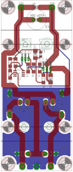
Here's the board i drew up, i used one of my templates for the mechanical side.
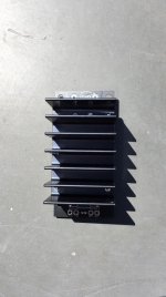
The heatsink is a RAD-A5723/50 good for 2.3K/W.
I used two TO220 diodes for full wave rectification, and two DO201 make up the other "Part" of the bridge.
Edit, i need to adjust the silk and the size of that plane on the bottom.
The heatsink is a RAD-A5723/50 good for 2.3K/W.
I used two TO220 diodes for full wave rectification, and two DO201 make up the other "Part" of the bridge.
Edit, i need to adjust the silk and the size of that plane on the bottom.
Attachments

Why not use a TO-92 style TL431 ?
And to get a higher voltage to drive the MOSFET gate one doesn't need much current.A simple doubler will do.
The LED was to have enough voltage to drive the mosfet.With a BJT that problem doesn't exist and you can loose more voltage on the driver.
Less disipation in the driver transistor and the TL431 and a resistor less.
Also more open loop gain.
Mona
Attachments
Last edited:
I went with the DIP8 version because i have some of them, and its height is less then that of the TO92 version, this board is meant to be mounted components down heat sink up to the wooden enclosure of the amplifier. in that case a zener diode beats a Led in height, so i will change to a zener diode.
The caps are at the side and the lettering for the pads is mirrored, so its on the bottom layer.
Attached a example from another project, i re-used the template for this board. The heatsink is glorious overkill for the job.
dimensions of the board: 120x50mm heatsink: 50x78x40mm
The caps are at the side and the lettering for the pads is mirrored, so its on the bottom layer.
Attached a example from another project, i re-used the template for this board. The heatsink is glorious overkill for the job.
dimensions of the board: 120x50mm heatsink: 50x78x40mm
Attachments
I posted a work-in-progress pcb😉
I will show you what i have come up with later today. I”m thinking of going SMD after all, as i really like MELF Resistors, i find that these solder quicker than their through hole 0207 counterparts.
As for the diodes, im thinking of leaving that configuration unchanged, so the module can be used with both center tapped and single winding transformers.
A small 10uF SMD ceramic cap over the zener should lower the zener noise right? Change out the base resistor in the previous version for 1K, i only included it to protect the diode base-emitter in the PNP driver.
The TTA006 i have in the 100s it seems to be electrically similar to the 2SA1837 which unfortunately went out of production.
Here's the SMD version, apart from the 1206 capacitor that is optional and the SOIC-8 TL431 (because i have a full reel). The Melf resistors are easy to solder.
Only the silk for the two filter caps is still on the topside, but mounting these on the bottom is easy enough.
I could add a LED to the output through a zener and resistor, so you can see if the voltage for any reason is too low on the output.
Gr,
Floris
Only the silk for the two filter caps is still on the topside, but mounting these on the bottom is easy enough.
I could add a LED to the output through a zener and resistor, so you can see if the voltage for any reason is too low on the output.
Gr,
Floris
Attachments
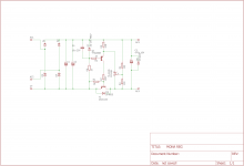
Why go back to a 1,5V "zener" (isn't a real zener)? Makes R5 much smaller resulting in less open loop gain and regulation.The higher the zener voltage the lower the voltage left for the TL431, as long as there is 3V (min.2,5V) it's allright.
R7 only takes some dissipation away from Q1, not very usefull.
If you want to get rid of noise of the zener a capacitor in parallel doesn't much, the Z of the zener is to low. Better the C after R2 at the base of Q1.
But who cares, a little noise in a heater circuit 🙂 .
Mona
R7 only takes some dissipation away from Q1, not very usefull.
If you want to get rid of noise of the zener a capacitor in parallel doesn't much, the Z of the zener is to low. Better the C after R2 at the base of Q1.
But who cares, a little noise in a heater circuit 🙂 .
Mona
True, i think it is good enough as-is for most applications. Would you mind if i do a group buy of these PCB's? If you want i can send you a pair + components.
Edit: R7 is there as a stopper resistor in case the 6144 likes to dance on its own, you're right it doesnt do much. I put 51R in there for convenience but 10R would also do the job
Edit: R7 is there as a stopper resistor in case the 6144 likes to dance on its own, you're right it doesnt do much. I put 51R in there for convenience but 10R would also do the job
- Home
- Amplifiers
- Tubes / Valves
- Tube heater voltage regulator