Do what you want, it's free world  😀
😀
Kind offer but no use to me.I'm old, in a home and rather disabled.
Mona
😀Kind offer but no use to me.I'm old, in a home and rather disabled.
Mona
OK i will think about a group buy, for now i am ordering 10 boards of which about 2 are available, so if anyone is interested i can supply those boards at a little over cost. How well the circuit works i wont know unless i build it.
Price per board will be below €5 each plus a small premium for soldering the SMD if you are unable to do this yourself. The rest of the parts i can supply as well at cost. I think realistically about €17,50-20 per module SMD soldered and all the parts, some i have on stock other parts im ordering today. The pcb can be used to mark out the drill holes on the heatsink.
This is a non commercial offer and covers the parts plus the petrol to the post office. Two heatsinks is €7 two boards is about €8 mounting hardware and SMD parts about €5 caps are €6 and €2 resp. Four transistors is €2 and various odds and ends €5 for two modules. Which leaves €10 for my time and energy.
If anyone is interested PM me.
easy to test for filament hum. put a DPDT switch in and switch the heater on/ off on the gain tube while it is running. if the hum disappears it's the heater power.
I am running a 6922 preamp (replace TA7136p) off the 8v dial light tap on the SX-780. I have a 106db s/n at 1 watt output.
I am running a 6922 preamp (replace TA7136p) off the 8v dial light tap on the SX-780. I have a 106db s/n at 1 watt output.
Helllo,
Many thanks for all for the sharing. I have few beginner noob questions, please.
I would like to use the post 30 rigth side circuitry for the IHT of an ECC8 in lieu of a lm317, so no need of trimpot to adjust a 6.3 Vdc ? (I wondered if the 200E on the shematic was for a sfernice pot resistor of 200 ohms ?
Could it be made on a verroboard with enough good behavior in spite of a pcb ?
What VAC and voltage secondary output should I use please ? the filament is 375mA and I use only one tube, so 6 to 8 V with more than 5VA is enough ?
Is there a delay behavior on it or a sorta of soft start that need to delay the start of B+ ?
Many thanks for your help.
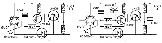
Ive copied the schematic under consideration by you.
The 200 Ohms sets the Constant current source current. Some current is then required for the TL431 to remain in regulation.
The 10K 15k divider sets the output voltage, the VREF of the TL431 is 2.49V so this allows you to calculate the circuit output voltage of approx 6.25V.
I have not breadboarded the circuit but i suggest an entirely different approach. and a different pass FET.
Its a nice circuit but one oversight is the lack of enough drive voltage for the FET. you could try RFP12N10L instead of the IRLN520
I will get back to you with an alternative circuit layout.
Cheers,
Florick/V4lve
Attachments
Thank you so much Florick.
Yep I read the thread several times and if I do not understand all, I have noticed all the further post30 parts choice enhancement and your further iterations.
Yep I read the thread several times and if I do not understand all, I have noticed all the further post30 parts choice enhancement and your further iterations.
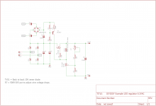
All-right, i had some time on my hands and decided to draw you a different supply,
This one uses voltage doubling using cheap components to provide +12V for driving the mosfet, and is easier to understand than the original schematic.
T2 BC557 is a rudimentary current source, but you can also use a 1K resistor instead. Both will work.
TL431 requires approx 1mA to stay in regulation.
Ive used 12N10L instead of the 520 device, you need to use a mosfet made for logic applications, i like the RFP12N10L because it has nice flat transfer curves, and DC SOA specified.
Attachments
Wow a special shematic for diyiggy😀. Wow many thanks for that and the didactic around.
It needs two secondaries ? Why the B1 graerte and c3, not possibe to biass r1 from the positive rail above c4 ?
It needs two secondaries ? Why the B1 graerte and c3, not possibe to biass r1 from the positive rail above c4 ?
It only needs one secondary, AC1 is connected to AC1 terminal and idem for AC2. Its a voltage multiplier using a second small bridge rectifier.
the reason you cannot do what you describe is that the FET requires say 4V with respects to source to conduct and this voltage has to come from somewhere. If you just take the rectified 6.3VAC and connect it to the gate, the output voltage can never be higher than (1.4x 6.3V-((Skottkey voltage drop)+(Threshold voltage Nfet)) ) say 8V minus 3V gives 5V output. you need that extra voltage higher than the output voltage to turn on the fet.
the reason you cannot do what you describe is that the FET requires say 4V with respects to source to conduct and this voltage has to come from somewhere. If you just take the rectified 6.3VAC and connect it to the gate, the output voltage can never be higher than (1.4x 6.3V-((Skottkey voltage drop)+(Threshold voltage Nfet)) ) say 8V minus 3V gives 5V output. you need that extra voltage higher than the output voltage to turn on the fet.

- Home
- Amplifiers
- Tubes / Valves
- Tube heater voltage regulator