Thanks for confirming the ground leak resistor. Would I be correct in assuming it's only required at the output terminals? Not required at the output of each cascaded pre stage, just final output?About the ground leak resistor a yes and it is for your own safety when disconnecting an tube output without ground leak resistor the output can charge a dangerous high voltage. I learned this just this summer.
Nice technics system.😎
That Technics is a beautiful concept
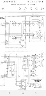
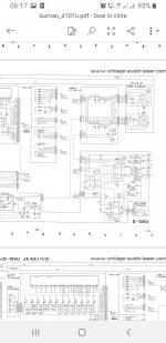
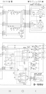
D103 doesn't show a clear cut schematic, D105 and d107 do it.
I wouldn't trust lampizator tastes...but he's the second guy to reedit Luxman's ideas, looking for the "tubey " sound...
http://www.lampizator.eu/lampizator/references/LUXMAN103/LUXMAN-D103u.html
As for what I'm supposed to say...I'm supposed to say nothing about things I don't see their point...
You may know this:
https://positive-feedback.com/audio-discourse/the-square-and-exponential-laws/
But you may have no ideea of this guy who went under the radar of any audiophile magazine for decades cause he was the best guy in the stage amplifier industry for decades although a highly intuitive guy about all trends:
Patt Quilter is the main founder of QSC and qsc amps take beneffit of some of the most inspired clipping protection circuit patented by Quilter.
And he had an intuition: bipolar trz are exponential devices so is capacitor's charge decay while the speaker is an inductance who's value depends on frequency:
https://www.cyberphysics.co.uk/topics/electricity/higher_electricity/capacitorDischarge.htm
So what's the result of using capacitors in series with an inductance and an exponential device? Why bootstraped driver stages behave more linear with the increase of the output signal and the distortions are smaller at higher power?
I wouldn't trust lampizator tastes...but he's the second guy to reedit Luxman's ideas, looking for the "tubey " sound...
http://www.lampizator.eu/lampizator/references/LUXMAN103/LUXMAN-D103u.html
As for what I'm supposed to say...I'm supposed to say nothing about things I don't see their point...
You may know this:
https://positive-feedback.com/audio-discourse/the-square-and-exponential-laws/
But you may have no ideea of this guy who went under the radar of any audiophile magazine for decades cause he was the best guy in the stage amplifier industry for decades although a highly intuitive guy about all trends:
And he had an intuition: bipolar trz are exponential devices so is capacitor's charge decay while the speaker is an inductance who's value depends on frequency:
https://www.cyberphysics.co.uk/topics/electricity/higher_electricity/capacitorDischarge.htm
So what's the result of using capacitors in series with an inductance and an exponential device? Why bootstraped driver stages behave more linear with the increase of the output signal and the distortions are smaller at higher power?
Attachments
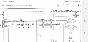
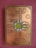
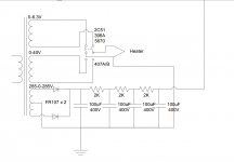
I would like to ask for help with my 5670 tube pre-amp. Someone produced me a PC board and look like it has some error on it.
The tube pin #1 and #9 which is the heater is connected together. Since the time I realized that I got discouraged. It is a simple pre-amp but I am familiar mostly DIY with semiconductors and not tubes.
Can someone help me to finish this project without burning or blowing up something. Thank you
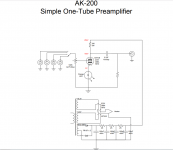
I post the schematics unfortunately The Grid stopper and Grid leak resistors are missing also. Some advise I need there to.
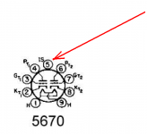
What do I do with pin number 5? 5670 has a 20V heater Voltage while the 369A, 2C51, 6N3 has 6.3V. The circuit was design with a toggle switch change the heater voltage. Should I connect PIN 5 to the ground? Please I need some help to complete these project , I have most of the parts for it.
Thank you
The tube pin #1 and #9 which is the heater is connected together. Since the time I realized that I got discouraged. It is a simple pre-amp but I am familiar mostly DIY with semiconductors and not tubes.
Can someone help me to finish this project without burning or blowing up something. Thank you
I post the schematics unfortunately The Grid stopper and Grid leak resistors are missing also. Some advise I need there to.
What do I do with pin number 5? 5670 has a 20V heater Voltage while the 369A, 2C51, 6N3 has 6.3V. The circuit was design with a toggle switch change the heater voltage. Should I connect PIN 5 to the ground? Please I need some help to complete these project , I have most of the parts for it.
Thank you
Attachments

Last edited:
5670 is 6.3V heater, not 20V. https://frank.pocnet.net/sheets/093/5/5670.pdf
Pin 5 is not connected or shield depending on the tube. It can be grounded.
Grid leak can be off of the board, grid stopper should have been put right by the grid pins.

Pin 5 is not connected or shield depending on the tube. It can be grounded.
Grid leak can be off of the board, grid stopper should have been put right by the grid pins.

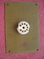
Yes, that is a good idea👍, I already cut the bad traces of the heater so pin 1 and 9 will be the +/- heater connections.Maybe you can isolate the problem thru holes with the dremel and point to point them correctly?
It will be not a beautiful layout but does not matter much. It will be inside the enclosure including the tube to.
Function, sound, stability it matter.
I don't know what to do with pin 5 (internal shielding) should I connect to the ground with a resistor or with out resistor or just leave it like that.
The rest I figured it out.
I have one more question. Someone suggested to increase the plate resistor value from 10K to 18K or so.
That improve the sound and stability(?) he said. I am not sure about that. At the moment I soldered the 10K there but I have 18K at home also.
Thank you
Attachments
I used a 6922 to drive the stock tone stack in pioneer sx 780. The first stage goes in front of the 100k volume pot.
Excellent results 125v B+ can drive 60v p-p
Excellent results 125v B+ can drive 60v p-p
- Home
- Amplifiers
- Tubes / Valves
- Tube flavour for 5.1 dual-purpose system