Definitely. I've yet to meet a single tone knob control wired otherwise.I'm wondering, is there any kind of standard as to which way a tilt tone control should work? More bass at full clockwise, or more treble? 😕
My first thought is more treble as you turn clockwise, which is usually the way the "tone" knob on a guitar is wired.
Thanks for the feedback!Definitely. I've yet to meet a single tone knob control wired otherwise.
-Gnobuddy
Have you ever tried that arrangement?Stereo pot.
Bass AND treble at the same time.
I've had the same idea, but never tried it out. I wonder if the inability to change the overall spectral balance (i.e. if it's too bright, you can't turn down the treble without also turning down the bass) might be too big a limitation?
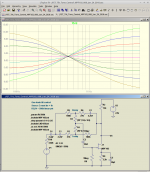
For the amp I'm building, I've settled on an active version of the "tilt" tone control, loosely related to the one used in the Big Muff Pi distortion pedal. It uses only one linear pot (500k in my case), and the active version has very nice-looking curves if you believe the LTSpice simulation (attached).
I thought I had attached this earlier in the thread, but if I did, I can't find it now, so I'll just attach it here.
This tone control needs to be fed from a buffer with low output impedance. I haven't shown that in the attached image.
I'm still tinkering with some of the component values (coupling and bypass caps, etc.), so this isn't necessarily the final version.
Also, don't trust the value of any source resistors in the LTSpice simulations. On the breadboard, I'm finding that my little collection of MPF102 JFETs wants very different-value source resistances than the MPF102 model in LTSpice does!
-Gnobuddy
Attachments
Have you ever tried that arrangement?
Not yet.
It depends on the chosen filter freqs.
Cut and boost would be nice.
And you can also roll back the treble on the guitar too, given it has not just only a volume pot.
So the high freq boost won`t be that much of a "problem" if not needed.
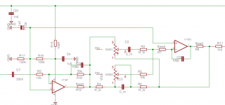
That's exactly what I did:Stereo pot.
Bass AND treble at the same time.
left pos: bass boost, treble cut
mid pos: linear
right pos: bass cut, treble boost
Thanks, voltwide!I just recorded a little demo:
<snip>
You have a lot of control range by the sound of it, and I bet it is very easy to adjust tone on the fly without losing your musical momentum. Nice work!
It took me a minute to wrap my head around your schematic, but then I recognized the well-loved active Baxandall circuit. I built my first one before I was fifteen years old (with a BC149 transistor, not an op-amp.) It is an old friend.
I have rarely seen an active Baxandall with the same-value potentiometer for both bass and treble, which you need to use a stereo pot the way you did. But I see Rod Elliott has such a design on his website ( Audio Designs With Opamps -2 )
The way you have your pots wired also makes a lot of sense to me. With simultaneous bass boost and treble cut at one end of the control range, you turned your Baxandall into a "tilt" control. (Maybe that's what Globalplayer had in mind as well, but I didn't realize that, and thought the idea was to have simultaneous bass and treble boost, or simultaneous bass and treble cut.)
I suspect that the tilt control I'm building (which I still haven't heard) will sound very similar to yours, minor differences in turnover frequencies and control range aside. One first-order RC low pass filter has pretty much the same-shaped frequency response as another!
-Gnobuddy
Well, initially I meant a bass and treble boost at the same time.
But after reading voltwide`s posts it seems to make more sense to boost the bass while cutting the treble.
Actually a very good/even better idea.
But after reading voltwide`s posts it seems to make more sense to boost the bass while cutting the treble.
Actually a very good/even better idea.
Yes, this is the well known Baxandall. I wonder why one should use different pot resistance for treble and bass, as far as I remember the hifi-standard was 10k Pots. (And 50k or 100k for the cheap and noisy mixing consoles).
I did the sound snippet on the fly, i.e. play some notes, turn the knob, and go on, no volume correction, no post processing. This demonstrates sound variation can be done immediately.😉
I did the sound snippet on the fly, i.e. play some notes, turn the knob, and go on, no volume correction, no post processing. This demonstrates sound variation can be done immediately.😉
The bass potentiometer is shorted out by the parallel capacitor (or two capacitors, in some variations of the circuit) at midband and higher frequencies. So at these higher frequencies, feedback is set to unity, by the two resistors at the ends of the bass pot, and these are typically ten times lower than the value of the bass pot itself.I wonder why one should use different pot resistance for treble and bass
So I had the impression that the treble pot (and associated resistors and capacitor) had to have impedances considerably lower than the ones in the bass network, in order to be able (at high frequencies) to overpower the unity-gain bass components and raise the gain above unity once more.
Virtually all the Baxandall and James active tone control circuits I saw during the years I was actively building Hi-Fi stuff did follow this sort of arrangement - the bass pot was always higher value than the treble pot - which reinforced my belief.
But clearly the thirteen or fourteen year old version of me misunderstood how this feedback network works, since I now know it is a fact that there are working tone controls of this type that use equal-value potentiometers!
Back then I knew nothing about using complex numbers to represent reactances, or loop equations to solve AC networks, so perhaps it's not too surprising my intuition led me astray.
The silly part is that I never re-visited the circuit to check my understanding of it, so apparently I still don't have the right internal mental picture of how it works.
Excellent, and exactly how a tone control should behave!I did the sound snippet on the fly, i.e. play some notes, turn the knob, and go on, no volume correction, no post processing. This demonstrates sound variation can be done immediately.😉
-Gnobuddy
cathode feedback to different inverter topologies...
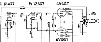
Surely these two feedback schemes shown below are equivalent in that they provide negative feedback over the stages shown.
The overall gain with feedback can be calculated from the open loop gain, including the transformer step-down voltage ratio, and the feedback ratio, using standard formulas from RDH, etc.
The output impedance likewise may be calculated based on calculating the effective plate resistance due to the feedback voltage and the gm of the output tube, in parallel with the internal plate resistance, and applying the impedance ratio of the OPT whilst adding in DC resistances, etc...
The schemes with presence control illustrate the effect of this feedback, which is to vary the damping factor of the system, including the amplifier output impedance and loudspeaker load impedance. It is to me a "hardening" of the sound that, while not unpleasant in itself, sometimes detracts from the smooth distortion tone. I don't always set the presence control at maximum. This tells me that some way of incorporating a varying amount of load feedback to a final tube stage is an important part of the tube amp experience.
The extra scratchiness of some presence controls is certainly due to the presence (!) of DC across the element; not as bad as DC across the wiper but still a source of noise. Easily improved by using the parallel DC/AC path scheme.
Attachments
Member
Joined 2009
Paid Member
For the amp I'm building, I've settled on an active version of the "tilt" tone control, loosely related to the one used in the Big Muff Pi distortion pedal. .
fyi The Big Muff tone control was first used by Supro (in their Thunderbolt amp - it'self a nice project perhaps), back in the 60's, before the Big Muff was conceived so that's where it should be attributed as far as I can see.
You may very well be right. You'll notice I didn't write "first used in the Big Muff Pi", though! 🙂...so that's where it should be attributed as far as I can see.
-Gnobuddy
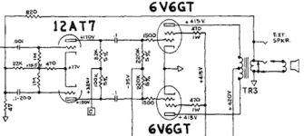
...12AT7 makes its first appearance as the pre-amp in the 6G15 Reverb unit in 1961.....
Well, here's a historical point.
Early TV sets often used 12AT7 as the RF amplifier.
It was good for that, but better tubes were possible. And would sell in weak-signal markets. Some also did better on strong signals, good for listeners in sight of the tower. 6BQ7, 6BK7, etc. By the late 1950s they were ubiquitous.
I believe the 12AT7 was going out of style (in the TV racket) right before the year you cite. But in high production for years before. So the warehouses were full when demand slacked. So price was cut. And somebody recalled that Leo bought a lot of twin-triodes, and made sure he knew of the bargain.
The 12AT7 was also used as the RF amp / mixer in FM radios. Around the same time frame (late 50's) a new tube was developed specifically for FM radio tuners, the 6DT8 / 12DT8. It retained the large size of the 12AT7 since it only needed to function at 108 MHz, while the 6BQ7 / 6BK7 / 6BZ7 family got the new shrunken size for use up to 216 MHz in VHF TV tuners. I vaguely remember another FM radio tuner tube, but I can't remember it's number.
I saw more 12AT7's in radios than TV's in my youth while shopping for tubes in the trash dump. I can remember seeing a 12AU7 or two in some smaller B&W TV sets. I believe they were used in the vertical sweep circuits.
I saw more 12AT7's in radios than TV's in my youth while shopping for tubes in the trash dump. I can remember seeing a 12AU7 or two in some smaller B&W TV sets. I believe they were used in the vertical sweep circuits.
Tubelab_com;5321818I vaguely remember another FM radio tuner tube said:Don't know about the US, but in Europe the standard for FM radio was the ECC85 (6AQ8).
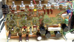
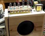
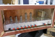
The 6AQ8 was not very common in the US. I did however make a screamer of a guitar amp using 3 X UCC85's (26AQ8) and 2 X UL84 (45B5). This board was lost for several years, but was recently found hiding in a partially finished cabinet that I had forgotten about. I will be firing it up and tweaking on it once I clear out some other projects.
Attachments


- Status
- Not open for further replies.
- Home
- Live Sound
- Instruments and Amps
- Tube Emulation & EQ