So a soul in Japan was thinking what merely 10cm can ever restrict...🙂
http://www.diyaudio.com/forums/powe...-voltage-shunt-regulator-546.html#post3195829
http://www.diyaudio.com/forums/powe...-voltage-shunt-regulator-546.html#post3195829
...Its not the milli Ohms, its the correction errors they create. The error amp corrects for another node essentially, a local one.
Well I wired up the remote sensing this morning, it definitely did not hurt anything, and I am trying to persuade myself that I hear no improvement whatsoever, but I'm not succeeding.. 😀
Anyway Nick, I think the SSHV2 is a very solid design and is technically excellent, drift is quite low, output impedance is as close to zero as I can imagine. (No audio present at all on the output.) Seems to work great with inductive loads. I'll be recommending it to anyone interested who'll listen.. (Most of my chatter seemingly goes over people's heads)
I would call it "elegant," and to the point it in no way detracts from the performance of my circuit design.. I have to be honest, I almost never, ever use anyone else's circuit designs in my own projects - the fact that it gets to stay is the biggest complement I can pay you.. 😀 😀
The Digital Bits (TPA Option)
The original dac digital design was done 4 yrs ago, and then I discovered I could purchase bare boards from TPA and modify them to accomplish my goals rather than make my own, so anyone can replicate the digital subsection by just purchasing those items. They could be purchased built and tested and then simply modified to reflect what I have done. (or not) 😀
Notes:
The WM8804 module was purchased assembled and tested from TPA.
Two raw COD boards were purchased and assembled by me with some modifications, here's what's relevant for purchased CODs:
- Configure one board for LEFT CH MONO MODE
- Configure one board for RIGHT CH MONO MODE
- Hard wire L- to R+, and R- to R+ (read PCM1784A data sheet if the why is not clear)
- Install a single pair of 2 - 5.1 ohm resistors on each board to do I/V conversion.
- Note that each channel is out of phase with the other, swap connections to transformer to compensate. It makes sense to configure so that the overall output phase of the DAC is non-inverting at the output.
- Insert 47 - 51 ohm resistors in series with each I2S output at the SPDIF receiver to provide proper series termination of the data buss, run from there to each dac board. (Bad things will happen otherwise - lock lost at higher sample rates, etc.)
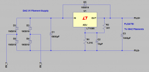
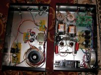
I've decided to leave the SSHV2 in the DAC chassis and built the supporting supplies in a matching chassis bought for the purpose.
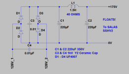
The power transformer is an Antec AS-05T120 (w/electrostatic shielding) which I have modified by winding an 11 turn secondary on top of it and connecting this to one of the filament secondaries. In addition I have connected the other filament secondary to boost the raw AC to the DC supply..
The power transformer is an Antec AS-05T120 (w/electrostatic shielding) which I have modified by winding an 11 turn secondary on top of it and connecting this to one of the filament secondaries. In addition I have connected the other filament secondary to boost the raw AC to the DC supply..
Attachments
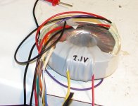
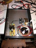
Here are some pictures of the more or less finished units. All power is controlled from the power supply module so I have only to flip the switch on the power supply to power up everything - this despite the fact that half the supplies reside in the DAC itself. (This was after all a respin of the analog section in my existing DAC.)
Attachments
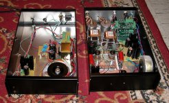
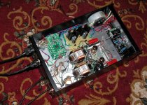
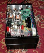
May I suggest you use 1200x900 attachments Kev? Those are not close ups, have inner work people might try follow. I am on 1920x1080 now and the details are a bit afar still.
I'll try to post some more detailed shots, and perhaps reprocess a few of these. I've kept them small because of bandwidth considerations at this end and a concern to keep them reasonably sized for other people on slow connections.
Having completed the power supplies satisfactorily when I have time I will attempt to do some overall performance measurements on the DAC. Subjective performance is good, but some scope time and actual measurements may reveal room for further improvements.
Good stuff here.

I'm sure everyone has seen me point to my web page on this, too many times, but how about another time 😀 Modifying CD player DAC circuits
Also a guy in Poland has been doing a lot more of this, see
Lampizator page index
An externally hosted image should be here but it was not working when we last tested it.
I've done things like this (replacing the op-amps with tubes in CD players), but I've used I/V resistors of around 100 ohms with good results, though with differing DAC chips from yours (PCM56, PCM61, TDA1543). Rotel used around 100 ohms on a PCM63 DAC chip's I output, which suggests that that chip works fine with 100 ohms to a virtual ground. See below (look between the DAC chip and the evil op-amp) 😀 :
I'm sure everyone has seen me point to my web page on this, too many times, but how about another time 😀 Modifying CD player DAC circuits
Also a guy in Poland has been doing a lot more of this, see
Lampizator page index
Last edited:
The PCM1794A in mono mode at full scale output is 15.6mA so with the 2 ohm resistors used the peak to peak signal is ~32mVpk. (Most of the older dacs cited are roughly 2mA at FS IIRC)
Based on testing presented in this thread: http://www.diyaudio.com/forums/digital-source/221743-testing-pcm1794.html it appears that values of up to 50 ohms for a single channel (not mono mode) caused no observable degradation at -1dBFS - for the PCM1794 in mono mode this would equate to about 25 ohms.
In the distant past I designed and built tube based I/V converters for PCM63 and AD1864.. The data sheet at the time for one of these devices stipulated a maximum compliance voltage of roughly 24mV on the current outputs, this specification was later removed from the respective data sheet and unfortunately I can no longer remember whether it was the AD1864 (likely) or the PCM63..
Keep us informed of your progress, Kevin.
I have a DAC with the PCM1796 that is a 4mA P-P output at full scale, much lower than your chip. I follow your lead and torture it with tubes and transformers to hear what comes out of it.
I have a DAC with the PCM1796 that is a 4mA P-P output at full scale, much lower than your chip. I follow your lead and torture it with tubes and transformers to hear what comes out of it.
Well I did a few measurements tonight and determined that the output currently is 2.1Vrms @ 0dBFS which is at least 3dB below my desired target. Frequency response is essentially flat from 20Hz - 15kHz and is down nearly 3dB by 20kHz which warrants further investigation since I was running at 96kHz at the time. The level was down a commensurate amount on the secondary of the 9545 so either I am doing something wrong with the configuration of my measurement hardware or the design is not capable of the bandwidth I expected. Next measurement session I will measure the output of the transformers disconnected from the miller capacitance of the 5842, and see if I was hallucinating 50kHz..
The transformers are driven by 2 ohm sources and loaded into 4.02K.. The secondary DCR is 1.8K so I am thinking I should run them a lot harder and change that shunt resistor back to 1.82K and remeasure the overall bandwidth.
Also I need to do some work on HF noise as there is a lot more of it than I expected to see, and I need not have worried about theoretical DNR as the noise kills everything below -60dBFS anyway, rather disappointing.
It does sound reasonably good from a subjective standpoint, linearity is definitely good based on measurements. More work is required.
Curious. I'd be surprised if your transformers didn't make 50Khz. I have quite a few and have not seen that as a problem - in fact I'd be happy if they stopped at 50Khz, but they don't. Maybe it is in the way you drive them, or the load on the secondary. Waiting to see what you find.
I thinking that leakage inductance given the much lower than recommended source impedance might be the culprit here. I'm going to increase the source impedance to something like 4-10 ohms and remeasure - it is a tradeoff though as I would like to keep the really good bass response I am getting. I believe I can go as high as 10 ohms while playing with the secondary loading to compensate. I will be completely satisfied if I can get to 20kHz -1dB, I'm not a bat and can't hear anywhere near that high. (My horn tweeters do very well to a little above 16kHz and then plunge like a cliff into the sea.. 😀)
In listening I identified another issue, and that is some discrete pops and ticks which were not present with the solid state iteration. There is some low level something... that subliminally bothers me as well, I will be looking for a cause there as well. (I observed a certain amount of very nasty looking low level [<2mV] HF noise [MHz] and will be looking to squash that as well.) I will be investigating grounding strategies and some other things tonight.
I'm assuming the ticks and pops are conducted noise from the server as I see no evidence of anything untoward on the bench. (Nice clean glitch free sines, and nice looking square waves at 440Hz and 1kHz as well)
It's kind of funny, I'm now a little more than a week away from the annual audio get together I host, and all summer the system worked and sounded great - as I approach the appointed time all sorts of things are going wrong, and not with just the new DAC design.. (Line stage has been a recent bete noire, and is having its own set of problems after the latest "upgrade" 😀)
(Line stage has been a recent bete noire, and is having its own set of problems after the latest "upgrade" 😀)Well there is some really good news on a couple of fronts.
The weird noise issue I reported was not in my imagination and I was able to trace it back to HF leakage and AC ground loop currents between the PC and the spdif receiver through the coax. The coax spdif input to the receiver board is not transformer coupled. I found that an extremely short wire from the ground side of the isolated BNC to chassis solved that problem. (Longer wire connected to the chassis further away did not work. 😱) I was able to observe a substantial reduction in HF noise on the analog outputs - this was enough to get me to a DNR of > 80dB so I am obviously rather pleased about that. (I was still able to see a clear if rather noisy sine at -80dBFS)
The HF performance was as I surmised affected by leakage inductance in the transformers. I increased the load resistors to 8.25K, boosting output levels to 2.6Vrms @ 0dBFS and here is the kicker response at 20kHz is now less than -1dB relative to 1kHz..
I'm using audiotester.de and am finding that despite a significant recent investment in hardware that is theoretically compatible with it, it is still hopelessly unstable. (WinXP Pro, Intel Pentium 4 3.0GHz HT with Intel Mobo and M Audio 24192) So good measurements aren't going to be forthcoming. 🙁 I think I am going to have to save my pennies for an older Audio Precision System 2 with digital option..
The dac in general sounds better, but I am still getting the odd tick and pop.. I don't believe the old version of the dac did this. (The digital section is largely unchanged, but I have had to make changes to the grounding and other details due to the new I/V section.) I'm using a Stello U3 asynchronous USB to spdif box (xmos based with the thesycon driver) and found in the past with the old dac that this worked a lot better than the M Audio spdif output, and supports 192K sample rate which the 2496 obviously does not.. This is frustrating..
🙂
I'm also wondering if these low level noises weren't always there and were masked by the apparent lack of resolution. I am hearing a great deal more detail both low level and background than previously, the other dac I have is a cheap solid state thing from SMSL, the SD-1955 which it doesn't reproduce most low level detail at all. I'm amazed at what it misses, and the THS4130 I/V sounded more dynamic but managed little if any more detail.. So it serves as a reference...
I suffered thru about a year of weird pops and clicks. Turned out to be a SPDIF ground loop, just like yours. (20' cable). A transformer fixed it.
So you have just increased the resistors on the secondary? Any change to the I/V resistor?
So you have just increased the resistors on the secondary? Any change to the I/V resistor?
I suffered thru about a year of weird pops and clicks. Turned out to be a SPDIF ground loop, just like yours. (20' cable). A transformer fixed it.
So you have just increased the resistors on the secondary? Any change to the I/V resistor?
Yeah, I'm planning to order a newava spdif transformer from digikey in my next order. The Stello is supposed to have one which I will verify before doing this.
I just basically doubled the load resistance on the secondary which is effective in addressing leakage inductance - I probably won't go over 12K or so. The leakage inductance creates a frequency selective attenuator, as the frequency goes up its reactance becomes appreciable compared to load resistance. The secondary of the 9545 has an inductance of 600H and there is electrostatic screening between the primary and secondary so the leakage inductance has to be appreciable. (Not to mention some capacitance which I have ignored) A simplistic model based on measurements seems to indicate roughly 41mH of leakage inductance - this still indicates a quality factor of >14000 which is rather good actually.
I'm going to order some additional resistors for the primary side, however increasing the source impedance driving the transformers will ultimately reduce the LF extension which is really good so I am not going too far down that road.
- Status
- Not open for further replies.
- Home
- Amplifiers
- Tubes / Valves
- Tube And Transformer I/V Converter For Differential Current DAC