Thanks Tony! 😀
This was about a six hour build from start to finish. I was a bit concerned about cannibalizing my dac but it worked out OK.
At some point I will do some measurements, but it is extremely quiet and FR peters out around the predicted bandwidth of the 9545 so I am pretty pleased.
the actual build itself does not take that long, it is the conceptualization, preparation of parts that does....
once you have all the parts on hand and every detail accounted for it is like a downhill run...
testing takes time, that is the phase that makes me break some sweat, sometimes i get scared and i have to overcome that to get myself turn on the switch.....😀
The longest part of the project was the actual wait for the 9545 to get here from England, and they came Saturday morning.
The funny thing is that the design I actually ended up building is nothing like what I had originally intended, or more accurately is only half of it..
The revised design evolved over an evening of thought, measurement and listening. I had envisioned a choke based mu follower, but the high dcr of the LL1667 and a profound lack of space said otherwise (24V battery...)
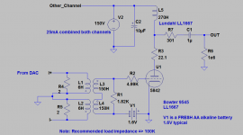
The actual current conversion is performed by the 2 ohm resistors and would need to be selected for desired output voltage, dac current output compliance voltage, acceptable noise performance and desired output level. My dacs are parallel mono PCM1794A which are uni-polar and idle at 8mA, so the FS swing is 16mApp per phase. The transformer primaries are driven separately by each phase of the dac output which is what Sowter basically recommends and although I suspect CMRR is slightly compromised by this connection I have not seen any evidence of it. (Much less HF noise than the previous implementation probably due to good CMRR, electrostatic shielding between primary and secondary, and controlled bandwidth) Anyway this results in approximately 100mVrms at the secondary and gain in the choke loaded amplifier stage is around 42 so I am pretty much in the target zone for gain.
I love battery bias, I used it in my phono stage as well, and it just works, alkaline batteries are quiet enough voltage sources and the few tens of milli-ohms of internal resistance is small enough to ignore, internal inductance is similarly small. Fresh alkaline batteries measure a little over 1.6V and lithium alkalines 1.9V which gives some flexibility for specific applications. They will last at least their rated shelf life.
I first used battery bias in a 6J7/6V6 pentode SE amplifier I designed a few years ago, those batteries are still sitting at slightly over 12V more or less exactly where they started.
The funny thing is that the design I actually ended up building is nothing like what I had originally intended, or more accurately is only half of it..
The revised design evolved over an evening of thought, measurement and listening. I had envisioned a choke based mu follower, but the high dcr of the LL1667 and a profound lack of space said otherwise (24V battery...)
The actual current conversion is performed by the 2 ohm resistors and would need to be selected for desired output voltage, dac current output compliance voltage, acceptable noise performance and desired output level. My dacs are parallel mono PCM1794A which are uni-polar and idle at 8mA, so the FS swing is 16mApp per phase. The transformer primaries are driven separately by each phase of the dac output which is what Sowter basically recommends and although I suspect CMRR is slightly compromised by this connection I have not seen any evidence of it. (Much less HF noise than the previous implementation probably due to good CMRR, electrostatic shielding between primary and secondary, and controlled bandwidth) Anyway this results in approximately 100mVrms at the secondary and gain in the choke loaded amplifier stage is around 42 so I am pretty much in the target zone for gain.
I love battery bias, I used it in my phono stage as well, and it just works, alkaline batteries are quiet enough voltage sources and the few tens of milli-ohms of internal resistance is small enough to ignore, internal inductance is similarly small. Fresh alkaline batteries measure a little over 1.6V and lithium alkalines 1.9V which gives some flexibility for specific applications. They will last at least their rated shelf life.
I first used battery bias in a 6J7/6V6 pentode SE amplifier I designed a few years ago, those batteries are still sitting at slightly over 12V more or less exactly where they started.
The amp is nice, I wanted to see what you did with the output stage of the DAC. I can figure it from your description, but if you have the schema handy, would love to see it.
Hi Mike,
There is no output stage in this dac, the PCM1794A outputs current which the 2 ohm resistors convert to voltage - all of it is done in the circuit I posted here, that is the entire analog path, all I have omitted is the connections to the specific pins on the dac IC... 😀
I can provide the connection information if your dac uses PCM1794A, in mono mode the outputs are cross connected and the overall output phase is dependent on whether you are outputting left or right - one channel inverted relative to the other channel, and the dac outputs inverted relative to each other. (It's a weird quirk of the internal architecture of the PCM1794A when non standard modes are selected. No question in my mind that the PCM1794A is the best hardware mode monolithic current output dac ic currently available.)
I do the summing in the current domain just by connecting the outputs together appropriately and the voltage conversion occurs in those tiny 2 ohm resistors.
@ Mike: I/V Circuit Updates
I've made a couple of minor changes that I think improve things sonically speaking. It was sounding a bit brash, and apparently it is not a bad idea to load the secondary of the transformer so I've added a 1.82K resistor in shunt across the transformer which also reduces the output by roughly 6dB which puts it more in the league of standard redbook levels.
I also changed the grid stopper to 4.99K which in conjunction with miller capacitance moves the -3dB of the amplifier stage to roughly 300kHz, but is highly dependent on the construction of the choke and in reality will probably be under 100kHz for most good chokes. The input transformer is about -2.2dB at 50kHz, but this is somewhat loading configuration dependent as well.
I'm putting together one of Nick' s SSHV2 regulators to power the tube electronics as given the low voltages this approach makes a lot of sense.
It seems to sound pretty good.. There definitely seems to be a little more resolution, fundamentally the changes are subtle on most material, just a little less congested sounding overall, a modicum more resolution.. Nothing of course I can reliably measure, and based on calculations using the circuit's internal noise sources it looks like I've slightly over 15bits of resolution or slightly more than 90dB which IMO is adequate for my purposes. The input grid stopper is a BIG contributor to that limitation, but for various reasons I think I prefer it that way, perhaps not.. I've added some details that will prevent the 5842 from turning into an oscillator or RFI detector with real world interconnects.
Edit (2013-01-11): Please see later posts for the most current schematic.. (!!)
Attachments
Thanks Kevin, nice to see what you've been up to. Yes, I imagine that the transformer is happier working into a heavy load. How did you arrive at 1.82K?
BudP and I have talked at length about the bandwidth of transformer output DACs. We seem to agree that ~50Khz is best, tho mine go much higher. I think limiting the circuit to about 50K keeps unwanted junk out of the signal.
In other news, I discovered today that if you connect the a triode's anode to its cathode, no music comes out. 🙁 Doesn't matter if you have B+ signal or whatever. Doh!
I've had a few of those doh moments myself.. 😀
The secondary dcr of the transformer is 1.8K and it seemed logical to try this value, I have a bunch of other resistor values, but the end result was quite good.. I originally tried much higher values (100K) which did not seem to significantly tame the brashness I commented about in a previous post. I assume the thing was ringing with some signal stimuli and the heavy loading killed it.
The Sowter application notes are ambiguously worded but initially I read something into them that seemed to imply 1.8K was a reasonable choice for a secondary load, upon rereading I could not figure out where I got that impression from, and deleted that resistor from the design prior to building it. Turns out the performance is a lot better with it than without, the implications are 6dB lower output level and effectively 3dB more noise relative to the new FS than before. Add my grid stopper and I guess I threw away at least a full bit+ of DNR.
I listened to it for several hours last night and it seems to acquit itself fairly well. I'm surprised with the clear reduction in performance that the 15 bit calculation implies that it still seems to resolve better than the analog path it replaced which was capable of at least 18 bit performance.
I can probably achieve a 16 bit DNR with a simple change to the grid stopper, but I will have to do some further calculations to see if that is in fact warranted, there may be other things that will then dominate.
My ears and the rest of the system (what audio system does?) cannot achieve a 16 bit DNR in any case.. My listening room on a quiet day has a residual noise floor of at least 20dBspl.. So... 😀
😀The secondary dcr of the transformer is 1.8K and it seemed logical to try this value, I have a bunch of other resistor values, but the end result was quite good.. I originally tried much higher values (100K) which did not seem to significantly tame the brashness I commented about in a previous post. I assume the thing was ringing with some signal stimuli and the heavy loading killed it.
The Sowter application notes are ambiguously worded but initially I read something into them that seemed to imply 1.8K was a reasonable choice for a secondary load, upon rereading I could not figure out where I got that impression from, and deleted that resistor from the design prior to building it. Turns out the performance is a lot better with it than without, the implications are 6dB lower output level and effectively 3dB more noise relative to the new FS than before. Add my grid stopper and I guess I threw away at least a full bit+ of DNR.
I listened to it for several hours last night and it seems to acquit itself fairly well. I'm surprised with the clear reduction in performance that the 15 bit calculation implies that it still seems to resolve better than the analog path it replaced which was capable of at least 18 bit performance.
I can probably achieve a 16 bit DNR with a simple change to the grid stopper, but I will have to do some further calculations to see if that is in fact warranted, there may be other things that will then dominate.
My ears and the rest of the system (what audio system does?) cannot achieve a 16 bit DNR in any case.. My listening room on a quiet day has a residual noise floor of at least 20dBspl.. So... 😀
That's pretty darn low. I don't know that my listening room is that quiet, despite all my work.
I usually load my DAC transformers with about 3.3K, but I'm not doing external I/V conversion as you are. Look for ringing and peaking, that's what you are trying to avoid. You probably have already.
I usually load my DAC transformers with about 3.3K, but I'm not doing external I/V conversion as you are. Look for ringing and peaking, that's what you are trying to avoid. You probably have already.
Yeah, the room is very quiet particularly late at night if there is no laundry being done, no TV in the living room, and our tea kettle, err steam boiler is not heating the house. Prime listening time is late evening through the early AM.. (Which not coincidentally is when I am most likely to be listening.. 😀 )
Depending on what dac IC you are using I probably have 2 - 4X the output current available unless you are using something like the PCM or DSD1794/A or AD1955 in mono.. The dacs I am using have always had outboard conversion, they are current output with no on board conversion at all so in this respect there is no change - from the dac perspective the only change is that they no longer work into a virtual earth but into a finite 2 ohm resistance..
Calculations do indicate that full 16 bit DNR is possible with this configuration, but just barely.. I'm not sure I am going to bother since I am relatively pleased with the overall performance at this point, and the difference is not likely to be audible.
The 9545 seems to reflect Sowter's current no compromise transformer design for I/V conversion and I thought was a better fit to my design goals that any of the Lundahl types I am familiar with.. I'm wondering what you are using?
I was listening to some Mercury Living Presence CD rips tonight (I generally much prefer the vinyl) that were remastered by Wilma Cozart Fine and have to say I have never heard them sound better, not quite as good as the vinyl where I have it, but a whole lot closer.. Again I think this points very strongly at the typical analog circuitry in a cd player or dac as not being up to snuff, and I find that very interesting.
I'm close but I feel like I need a few more dB of output and in conjunction with that change I can make a few others to get the analog path DNR up to a theoretical 16 bits at least from a noise perspective.
I think the Sowter transformers may have some sort of break in mechanism like the LL1941 appear to have. The Lundahls were pretty dreadful when first pressed into service, and then one day they weren't, and it wasn't a matter of my getting used to them, in non blind A/B with myself and a couple of others the previously preferred device no longer was, reverse of expectation bias if you will.. JK 😀
I'm still waiting for the power supply transformer, the film caps and I have yet to order the chassis so I have not had a chance to evaluate the SSHV2 yet. I did build up the board yesterday evening and it is almost ready to go except for the other required parts.
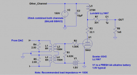
Some changes to increase output level roughly 3dB putting it more or less exactly where I need it, and a change in the value of the grid stopper which has a significant effect on the SNR and hence effective DNR of the overall dac.
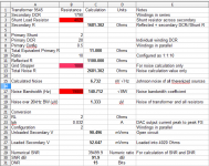
Rigorous calculations with the changes indicate a DNR of 15bits, and an SNR of over 91dB, this probably represents a real improvement of roughly 2 - 3dB in reality over the previous less rigorously calculated values. Not a huge change overall.
It does not appear likely that I will achieve a DNR of 16 bits with the current design although I am relatively close, the tradeoffs I made in order to keep the dac in an output voltage range that does not exceed its undisclosed voltage compliance range dictate something reasonably close to these values, even with a completely unloaded secondary I will not achieve a 16 bit dnr unless I increased the value of the shunt resistors across the inputs significantly - I believe the upper limit for the transformer before the performance starts to audibly degrade is < 20 ohms with parallel PCM1794A based on experimentation. (The tradeoffs being rapidly rising distortion in both the transformer and following amplifier stage, and excessively high output levels.)
The 5842 equivalent input noise resistance has been ignored because it is inconsequential compared to the Johnson noise generated by the primary and secondary windings of the 9545. The effect of the grid stopper has been figured in, and is significant. Output circuit resistances are not very significant noise contributors based on the values present and the signal levels in the plate circuit.
Note that the grid stopper R2 has a significant impact on stability and it may be reasonable to increase it to as much as 2.21K which will not very significantly affect the DNR.
Edit (2013-01-11): Please see later posts for current schematic. (!!)
Attachments
I spent a number of hours listening without any particular desire to make further changes. The bass is not quite there quality wise yet, but I will wait to see what effect the SSHV2 has on that. Given the plate chokes DCR of 2.4K and inductance of 270H I would not expect an earth shattering difference, but the old Heath Kit supply has 47 yr old electrolytic caps in it still, (I need to do something about that) and probably has a much higher source impedance than I have considered
Waiting for a few parts to get here for the SSHV2 which I will try next, fly wired temporarily for testing prior to the chassis arrival.
I'm going to use an Antek toroid with electrostatic shield, and may wind some additional turns on it to boost the 6.3V windings for use with a filament regulator. The filament regulator will be built around a single LT1086 since the current required is just 600mA, and the low drop voltage makes this part attractive.
The caps for the SSHV2 came today, now I am just awaiting the chassis, some parts from Digikey, and the power transformer. Still have to order some electrolytic high voltage caps.. I'll do that probably over the week-end if not sooner.
I'm listening to analog tonight for the first time in a week, and subjectively speaking the performance of the new I/V converter is a considerable step up compared to the THS4130 and UTC A-20 transformers.
I'm listening to analog tonight for the first time in a week, and subjectively speaking the performance of the new I/V converter is a considerable step up compared to the THS4130 and UTC A-20 transformers.
Attachments
SSHV2 Installed
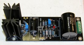
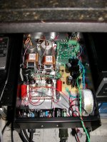
Decided that it made sense to install the regulator in the chassis with the rest of the dac. Wish I could fit the rest of it in this box, the HV toroid, rectifiers, choke, and filter caps along with the filament regulator are going to have to go in the second chassis. Believe it not since I have dedicated analog and digital AC power lines I'm going to run the analog portion of the dac on the analog supply line.. 😀
Got it all hooked up and made the required adjustments. The CCS portion is adjusted to 45mA, and the shunt to 150V, it was very easy to adjust. It came up immediately and works fine. Since the loads are chokes the changes are subtle, but overall better and my perception is the bass quality is significantly improved.
More listening impressions over the week-end. I've included a picture of the regulator installed.
Attachments
Gave you no hassle and it snugged nicely in its corner, good. Can't see well, is it "Kelvin" 4 wire output connected, or "Kevin" 2 wire connected?😀
but the old Heath Kit supply has 47 yr old electrolytic caps in it still, (I need to do something about that)
You think? 😀 maybe they made the to last back then 😉
Tony.
Gave you no hassle and it snugged nicely in its corner, good. Can't see well, is it "Kelvin" 4 wire output connected, or "Kevin" 2 wire connected?😀
Hi Nick,
It is the "Kevin" connection, and Lord Kelvin is turning over in his grave.. 😱 😀 I'm a big fan of the Kelvin connection, but the entire loop length is less than 30cm, it was >1AM in the morning, I'm lazy, and I figured that a few additional milli-ohms was not going to be a big deal, had I installed it in the yet to arrive power supply chassis as originally planned I would have used the Kelvin connection.. 😀
I'm going to add a pair of additional wires for the Kelvin option tomorrow evening - should take a few minutes at most. I don't expect it to be audible given the short distance to the load, but since the option is there I'm going to use it. 😀
Given how good the bass sounded at low levels I would say that the SSHV2 probably has addressed my concerns about bass quality. Tomorrow night I will crank it up to relatively insane levels and see.. 😛
One thing that is clear is that it would have been better I think to start with an entirely new and slightly larger chassis, this project has a very kludgy feel to it, all of the vacated holes and the screw through the front panel contribute to that impression.
The other thing I've noticed is that at 150V out and 25mA of load current (CCS set to 45mA) nothing gets very warm at all. Nice conservative design, and I think one assured of a good long service life, concerns over reliability and a rather wretched experience servicing hybrid ARC gear years ago has had me avoiding semi-conductors except in filament regulators.
- Status
- Not open for further replies.
- Home
- Amplifiers
- Tubes / Valves
- Tube And Transformer I/V Converter For Differential Current DAC